Dynojet 424 Linx: DWRT Installation Guide User Manual
Page 29
4 2 4 L I N X I N S T A L L A T I O N
Pulley Mounting Plates and Outer Bearings Installation
Version 6
Linx Installation for Model 424 Automotive Dynamometers
25
7
Remove the 1/4-20 x 1.75-inch cap screws from the splined shaft.
8
Verify the splined shaft will slide in and out of the dyno splines easily once all the
bolts are tightened.
Note: The splined shaft must easily slide in and out of the dyno splines in order
to engage and disengage the Linx belt drive.
9
Using the installation instructions included with the bearing, secure the lock
collars of both bearings.
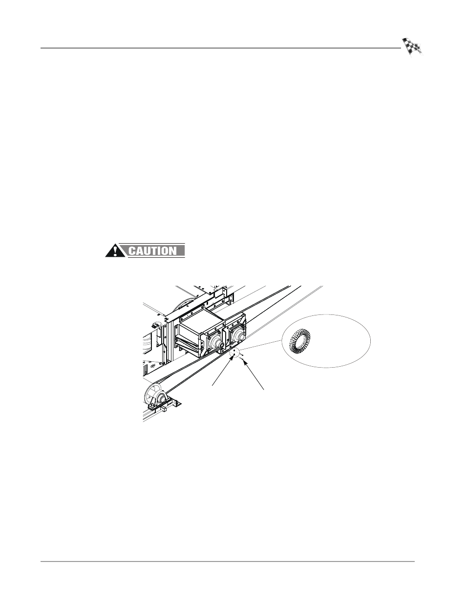
10 Using two 1/4-inch lock washers, replace the 1/4-20 x 1.75-inch cap screws.
11 Tighten the 1/4-20 x 1.75-inch cap screws to 7 ft.-lb. (9.5Nm).
Note: A gap will remain between the splined shaft flange and outer shaft.
Note: The lock washer is comprised of two individual pieces. Should the washer
separate, verify the pieces go back together with the serrated edges facing
outward as shown in Figure 22.
12 Secure the cap screws with the shaft safety wire. Refer to Appendix C for
installation instructions.
Failure to secure the cap screws with safety wire can result in damage to the
dyno and/or the vehicle.
Figure 22: Install the Cap Screws and Lock Washers
XD068
lock washer
serrated edges
facing outward
lock washer
cap screw