Dynojet 424 Linx: DWRT Installation Guide User Manual
Page 18
Linx Installation for Model 424 Automotive Dynamometers
4 2 4 L I N X I N S T A L L A T I O N
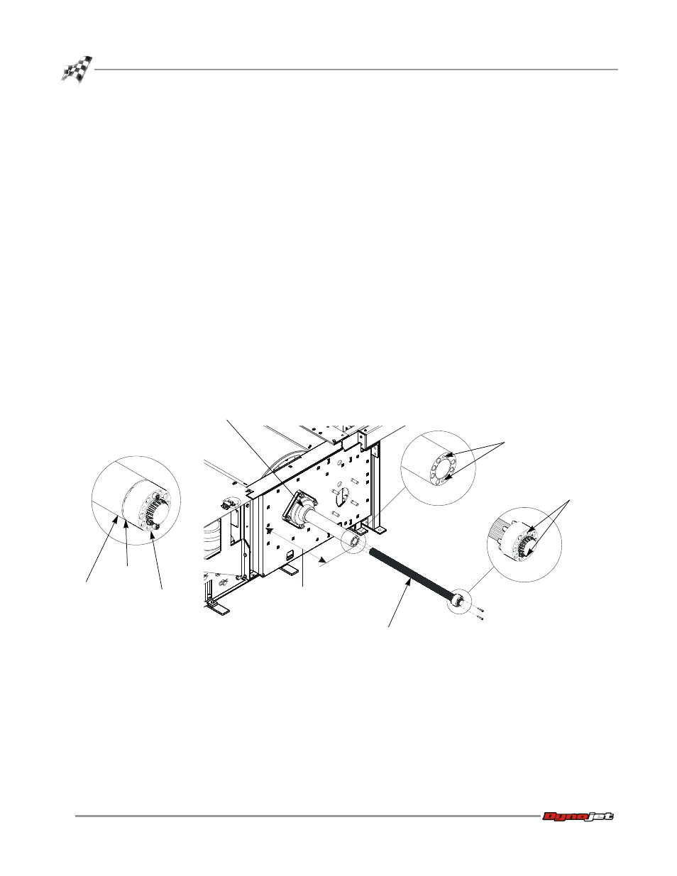
Flange Bearing, Outer Shaft, and Splined Shaft Installation
14
4
The distance from the face of the bearing mounting plate to the end of the outer
shaft should be approximately 16.125-inches.
5
Apply a small amount of grease to the first two inches of the splined shaft.
6
Slide the splined shaft through the outer shaft and into the splines in the dyno
drum.
7
Align the two unthreaded holes in the splined shaft flange with the two threaded
holes in the outer shaft.
8
Insert two 1/4-20 x 1.75-inch cap screws and tighten them just enough so the
tapered pins are engaged with the tapered holes.
Note: A gap will remain between the splined shaft flange and outer shaft.
9
While applying just enough upward pressure to support the shaft, tighten the
four 9/16-inch nuts.
10 Remove the two 1/4-20 x 1.75-inch cap screws.
11 Once the four 9/16-inch nuts are tight, it should be very easy to slide the splined
shaft in and out of the dyno splines.
12 Replace the 1/4-20 x 1.75-inch cap screws.
13 Confirm the outer shaft is 16 1/8-inches from the mounting plate.
14 Using the installation instructions included with the bearing, secure the lock
collar.
Figure 10: Measure the Outer Shaft and Test Install the Splined Shaft
XD086
lock collar
threaded holes
splined shaft
unthreaded holes
outer shaft
splined shaft
flange
gap
16 1/8-inches