Dynojet 424 Linx: DWRT Installation Guide User Manual
Page 17
4 2 4 L I N X I N S T A L L A T I O N
Flange Bearing, Outer Shaft, and Splined Shaft Installation
Version 6
Linx Installation for Model 424 Automotive Dynamometers
13
. . . . . . . . . . . . . . . . . . . . . . . . . . . . . . . . . . .
FLANGE BEARING, OUTER SHAFT, AND SPLINED SHAFT INSTALLATION
Use the following instructions to install the flange bearing, splined shaft, and outer
shaft on both the moveable and stationary dynos.
You will need the following parts:
• 32300001
Flange Bearing with Lock Collar (2)
• 36500016
Screw, 1/4-20 x 1.75", SHCS, Drilled (4)
• 36711100
Nut, 9/16-12, Hex (8)
• 36943101
Washer, 9/16", Flat (8)
• 61300030
Drive Pulley Shaft (Outer Shaft) (2)
• 62200006
Splined Shaft (2)
1
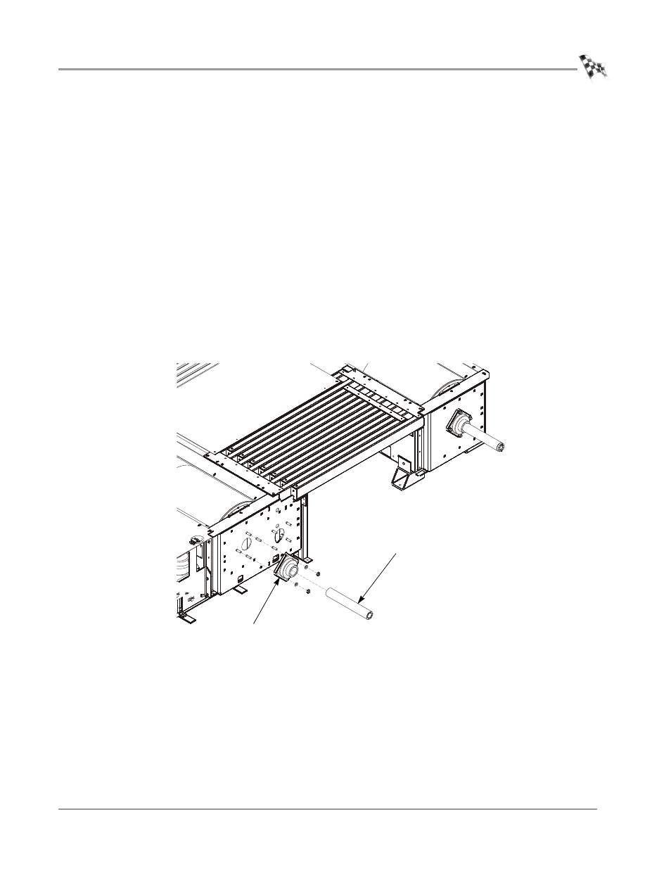
Place the flange bearing on the threaded studs on the inner plate.
2
Loosely secure the flange bearing to the inner plate using four 9/16-inch washers
and four 9/16-inch nuts.
3
Slide the outer shaft into the bearing.
Figure 9: Install the Flange Bearing and Outer Shaft
XD049
flange bearing
outer shaft
- 150: Kart and ATV Dynamometers (44 pages)
- 150: Dyno Drum Cover for Kart and ATV Dyno Motorcycle Option (3 pages)
- 150: WinPEP 7 (170 pages)
- 168: Eddy Current Brake (27 pages)
- 200: Eddy Current Brake (45 pages)
- 200: Replacing the Starter Ring Gear (7 pages)
- 200: Safety Switch (3 pages)
- 200: DynoWare EX+ Upgrade Installation Guide for Motorcycle Dynos (20 pages)
- 200: Throttle Stop (3 pages)
- 200: Eddy Current Brake Driveline Upgrade (17 pages)
- 200i: High Pressure Blower (20 pages)
- 200: Installation Guide (73 pages)
- 200i: Pit Installation Guide (154 pages)
- 200i: Pre-Installation Guide (52 pages)
- 200i: Installation Guide (184 pages)
- 200i: Air Brake and EEC Kit (40 pages)
- 200i: Dynamometer Wiring Schematic (2 pages)
- 200i: Folding Ramp (15 pages)
- 200i: Control Panel Interface Upgrade (S/N 201xxxx) (31 pages)
- 200i: Control Panel Interface Upgrade (S/N 202xxxx) (29 pages)
- 200i: Motorcycle Exhaust Extraction System Drawings (18 pages)
- 200iP: Pit Installation Guide (148 pages)
- 200iPX: Installation Guide (163 pages)
- 200iPX: Installation Guide (52 pages)
- 200ix: Pit Installation Guide (163 pages)
- 200ix: Extended Carriage and Trike Adapter Assembly (15 pages)
- 200iX: Upgrade Installation Guide (56 pages)
- 200ix: Extended Carriage with Trike Adapter Assembly (13 pages)
- 224: CE Package (17 pages)
- 224: Maintenance Guide (35 pages)
- 224: Installation Guide (78 pages)
- 224/4WD: Installation Guide (77 pages)
- 224: Pit Installation Guide (56 pages)
- 224x: Above Ground Four Post Lift Dimensions (1 page)
- 224x: Pre-Installation Guide (63 pages)
- 224x: 4WD Dyno Air and Wiring Schematic (2 pages)
- 224: Eddy Current Brake (73 pages)
- 224: Pit Eddy Current Brake (69 pages)
- 224xLC2: Quickstart guide for DWRT (2 pages)
- 248: Pit Installation Guide (74 pages)
- 248: Installation Guide (58 pages)
- 248: DynoTRAC User Guide with Variable Brake (14 pages)
- 248: DynoWare EX+ Upgrade (22 pages)
- 248: Optical RPM Sensor (22 pages)
- 248: Proportional Air Brake (21 pages)