Connecting the audio, sensor and relay device, 3 connecting the audio, sensor and relay device – AVer EXR6004-WiFi User Manual
Page 14
8
1.4.3
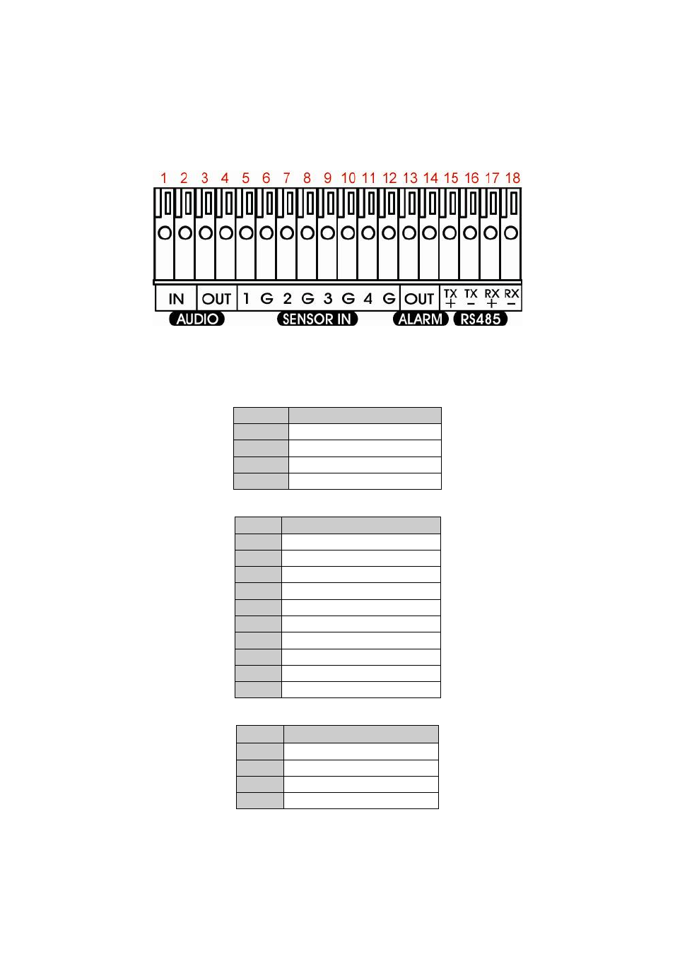
Connecting the Audio, Sensor and Relay device
The Sensor, Alarm, and audio port enable you to connect 4 sensor inputs, 1 relay outputs, and 1 audio in
and 1 audio out device. Just connect the external sensor, relay, and audio in/out device pin directly to the
pinhole. The RS-485 port can be used for POS system connection through an AVerDiGi Data Box.
Check the table below and locate which pinhole is assigned to sensor input, relay output, and audio
in/out.
The signal from the sensor (i.e., infrared sensors, smoke detectors, proximity sensors, door sensors, etc.)
is being transmitted to the unit and this triggers the system to respond and send signal to relay device (i.e.,
alarm, telephone etc).
Audio in and out pinhole:
Pin #
Definition
1
Audio input signal
2
Audio Ground signal
3
Audio output signal
4
Audio Ground signal
Sensor and Alarm pinhole:
Pin #
Definition
5
Sensor 1 signal
6
Sensor 1 Ground signal
7
Sensor 2 signal
8
Sensor 2 Ground signal
9
Sensor 3 signal
10
Sensor 3 Ground signal
11
Sensor 4 signal
12
Sensor 4 Ground signal
13
Relay signal
14
Relay signal
RS-485 pinhole:
Pin #
Definition
15
RS485 TX+ signal
16
RS485 TX- signal
17
RS485 RX+ signal
18
RS485 RX- signal