69373g ssthruhullscupper – Attwood Stainless Steel Scupper Valves User Manual
Page 2
Stainless Steel Thru-Hulls
and Scupper Valve
Installation Instructions
66540 - 66557, 66576 - 66579 and 67550-67580 Series
SAVE THESE INSTRUCTIONS
Form Number 69373 Rev G
08-03
This product carries a limited Lifetime Warranty.
See www.attwoodmarine.com or Product Catalog for details.
WARNING:
Read all instructions carefully before installing and using this product. To
prevent injury, remove boat from water when installing this product and
before using 120V power tools.
The stainless steel Thru-Hull and Scupper Valve must be mounted above
the boat’s maximum water line as determined by the boat’s draft at the
maximum loading recommended by the boat manufacturer. On sailboats,
mount the thru-hull high enough on the center of the transom to be above
the water line at all times.
REQUIRED FOR INSTALLATION
• Expandable wrench (max. 2-1/2", 64mm)
• Hole saw (see chart for size)
• Cordless drill
• Polyurethane marine sealant
THRU-HULL INSTALLATION
Thru-Hull
Thread
Hose
Hole Saw
Max. Hull
Part Number
Length
I.D.
Size
Thickness
66540-1 Short
5/8"
I.D. 1-1/8"
5/8"
66546-1 Standard 5/8"
I.D. 1-1/8" 1-1/16"
66541-1 Short
3/4"
I.D. 1-1/8"
5/8"
66547-1 Standard 3/4"
I.D. 1-1/8" 1-5/8"
66542-1 Short
1"
I.D. 1-1/2"
5/8"
66548-1 Standard 1"
I.D. 1-1/2" 1-3/4"
66543-1 Short
1-1/8"
I.D.
1-1/2"
5/8"
66549-1 Standard 1-1/8"
I.D.
1-1/2" 1-3/4"
66544-1 Short
1-1/4"
I.D.
1-3/4"
5/8"
66550-1 Standard 1-1/4"
I.D.
1-3/4" 1-7/8"
66545-1 Short
1-1/2"
I.D. 2"
5/8"
66551-1 Standard 1-1/2"
I.D. 2"
1-7/8"
66552-1 Standard
2"
2-1/2"
2"
90° Thru-Hull
Part Number
66576-1 Standard 5/8"
I.D. 1-1/4" 1-1/16"
66577-1 Standard 3/4"
I.D. 1-1/4" 1-1/16"
66578-1 Standard 1"
I.D. 1-5/8" 1-1/4"
66579-1 Standard 1-1/8"
I.D.
1-5/8" 1-1/4"
Narrow-Flange Thru-Hull
Part Number
67555-1 Standard 5/8"
I.D. 1-5/16"
7/8"
67554-1 Standard 3/4"
I.D. 1-5/16"
3/4"
67556-1 Standard 1"
I.D. 1-5/16"
7/8"
67557-1 Standard 1-1/8"
I.D.
1-5/16"
3/4"
67551-1 Standard 1-1/2"
I.D. 2"
1"
2-1/2"
67558-1 Long
3/4"
I.D. 1-5/16"
(min.1-9/16")
2-1/2"
67562-1 Long
1-1/2"
I.D.
1-15/16"
(min.1-9/16")
2-1/2"
67561-1 Long
1-1/8"
I.D.
1-5/16"
(min.1-9/16")
Mount Thru-Hull in the transom or side of hull, at least 12" (305mm) above
maximum water line. If possible, place fi tting on the same side as the
steering wheel so the driver can see discharge of water when the pump
is working properly.
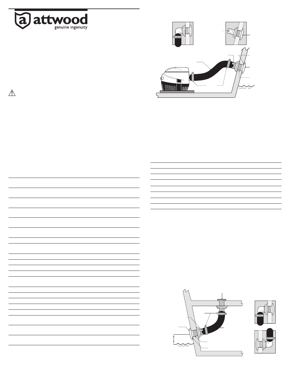
1. Use a hole saw (see chart above for size – check against thru-hull) to
cut hole in the transom or hull. (See Figure 1)
Figure 1
Hose
Clamps
Maximum
Water Line
Marine Sealant
Thru-Hull
(standard thread)
See Chart for
Hole Saw Size
Shaft Wrench Fitting
Hose at Upward Angle
Notch for
Tightening
Thru-Hull
(short thread)
© 2008 Attwood Corporation
1016 N. Monroe Street, Lowell, MI 49331-0260 www.attwoodmarine.com
2. Remove tightening nut. Apply a small bead of marine sealant in the
groove under the Thru-Hull fl ange.
3. Place Thru-Hull into the hole. After this point, all connections may be
made from inside the hull.
4. Place tightening nut onto threads, with wide side toward hull. Tighten
fi rmly, but do not damage gelcoat by overtightening. To prevent turning,
grip the Shaft Wrench Fitting (on Standard Thread models) or the
Notched End (on Short Thread models).
5. Lead hose from bilge pump to Thru-Hull at an upward angle. Fasten
tightly at both ends with hose clamps.
SCUPPER VALVE INSTALLATION
Scupper Valve Thread
Hose
Hole Saw
Max. Hull
Part Number
Length
I.D.
Size
Thickness
66557-1 Short
1-1/2"
I.D. 2"
1-7/8"
66553-1 Standard 1-1/2"
I.D. 2"
3"
66555-1 Standard 2"
I.D. 2-1/2"
2"
67553-1 Standard
1-1/2"
I.D.
2-1/8" 2-3/4"
67581-1 Standard 1-1/2" 2-3/8" 1-1/8"
67580-1 Standard
2"
2-3/8" 1-1/8"
67583-1 Standard 2-1/2" 3-5/8" 1-1/2"
67582-1 Standard
3"
3-5/8" 1-1/2"
The Attwood Stainless Steel Scupper Valve is designed for boats with a
self-bailing cockpit. The fl apper valve opens outward to allow water to exit
and automatically closes to help prevent backwash from entering the cockpit.
Mount Scupper in the transom at least 12" (305mm) above maximum
water line.
1. Use a hole saw (see chart above for size - check against scupper) to
cut hole in the transom or hull. (See Figure 2.)
2. Remove tightening nut. Apply a small bead of marine sealant in the
groove under the Scupper fl ange.
3. Place Scupper Valve into the hole. After this point, all connections may
be made from inside the hull.
4. Place tightening nut onto threads, with wide side toward hull. Tighten
fi rmly, but do not damage gelcoat by overtightening. To prevent turning,
grip the Shaft Wrench Fitting with an expandable wrench.
5. Lead hose (see chart above for size) from cockpit to Scupper at a
downward angle. Fasten tightly at both ends with hose clamps.
Cockpit
Cockpit Drain (#3882-1)
Hose
Clamps
Scupper Valve
At Least
12" Above
Maximum
Water Line
Marine Sealant
Shaft Wrench Fitting
See Chart
Hole Saw Size
Hose
Figure 2