Attwood 238 Series Seat Mounts User Manual
Installation instructions
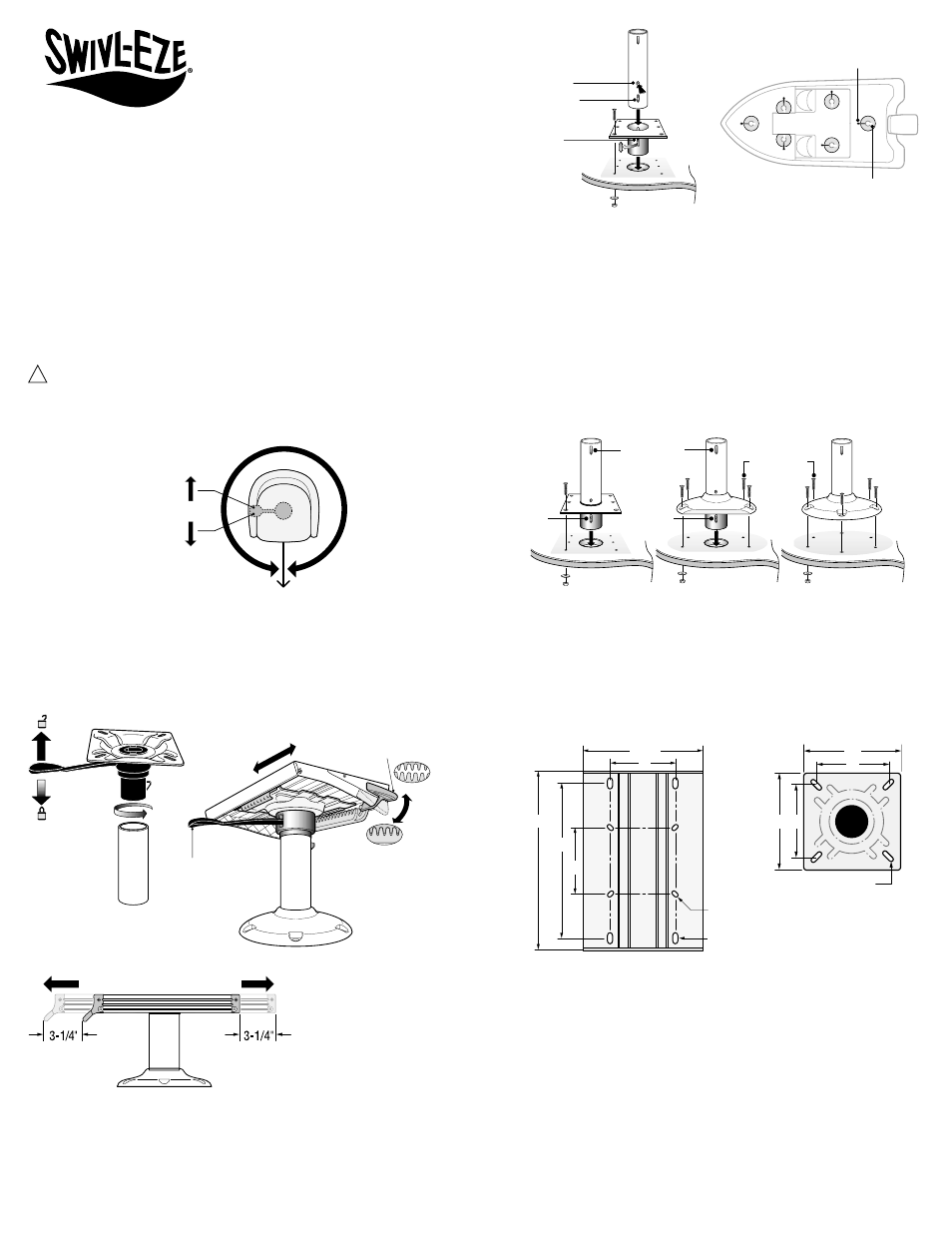
Figure 4
Figure 5
Figure 3
Figure 2
2. On slider platform, slide handle must be beneath front of seat. Adjust slider platform
fore/aft so that front edge is even with front of seat. Handle will be slightly exposed.
3. Insert 1/4"-20 stainless steel machine screws through washers and the widest pat-
tern that matches T-nuts in bottom of seat.
Be sure at least 3/8" (8mm) thread length enters the seat’s T-nuts.
4. If seat does not have T-nuts, it must be securely thru-bolted with 1/4" stainless
bolts, washers and nuts.
5. When seat is fastened reinsert into the pedestal tube and press all the way down.
Check for pivot, slide, and locking operations.
MAINTENANCE
1. Clean pedestal and mount with mild soap and water. Do not use abrasive
cleansers or polishing agents.
2. Periodically check all fasteners for proper tightness.
2. For Socket bases only: drill 3-1/2" deep x 3-1/4" dia. (89 x 89mm) hole at exact
center of mounting location.
3. For Square and D-Shape Socket bases: remove one plastic knockout so correct
slot is open for forward locking position.
4. Turn base so pedestal tube slot is opposite the Auto Lock handle side.
5. Use base as template to mark and drill 5/16" (8mm) holes through deck and substrate.
6. Thru-bolt the base with stainless steel 1/4"-20 countersunk-head machine screws,
washers, and nuts.
FASTEN SEAT TO PEDESTAL
1. Place seat mount or slider platform against bottom of the seat. (Figure 5)
MATERIALS REQUIRED FOR INSTALLATION
• Six (6) 1/4"-20 stainless countersunk-head machine screws, washers and nuts.
Bolts must be suitable length for mounting location and substrate.
NOTE: Do not use copper or copper-plated fasteners.
• Four (4) 1/4"-20 stainless steel machine screws and washers to attach seat to mount.
MOUNTING LOCATION AND HEIGHT
• Best sitting height (including seat) is about 15-1/2" (39cm) above deck.
• Pedestal must be mounted to a suitable marine-grade substrate according to
ABYC standards.
• Aluminum or stainless steel backing plate is also recommended.
PEDESTAL BASE INSTALLATION INSTRUCTIONS
1. Lift Auto Lock handle to unlock the seat mount; remove it from pedestal tube.
IMPORTANT: Pedestal base orientation determines the correct direction of the seat
tilt and Auto Lock handle. Before fastening, the base slot must be positioned on the
side opposite the Auto Lock Handle (Figure 4).
To Operate Slider Platform Handle:
1. Lift handle to allow fore-aft motion. (Figure 2)
2. Release handle to hold slider in place. Fully lock by pushing handle down.
To Remove / Relocate Pedestal Tube from Socket Base:
1. To insert pedestal tube: Align Locking Latch with Base Slot. Press down until the
latch locks. Try to lift tube to be certain it is locked in place. (Figure 3)
2. To remove pedestal tube: Depress button at bottom of tube. Twist and lift to
remove tube.
To Operate Auto Lock Handle:
1. Lift Auto Lock handle to unlock and pivot.
2. When you release handle, seat will automatically lock forward as you rotate to
forward position (Figure 2).
NOTE: Seat must be locked forward when vessel is in motion.
Figure 1
PEDESTAL FEATURES
Swivl-Eze 238 Series Pedestals offer ergonomic controls and smooth, wobble-free
motion. They meet Type A Driver ABYC H-31 regulations for driver’s seat applications.
Installers and users must abide by all ABYC and U.S. Coast Guard regulations for seating.
Pedestal is ordered with Auto Lock handle at Left, Right, or (on Seat Mount versions)
Forward. Handle can’t be modified to a different orientation.
HOW TO USE THE PEDESTAL
WARNING
According to ABYC and Coast Guard regulations, when the vessel is in motion, seat
must face forward with Auto Lock handle engaged (Figure 1).
SAVE THESE INSTRUCTIONS
Form Number 69400 Rev. B
04-04
238 Series 2-3/8" Diameter
Bell and Socket Pedestals
Installation Instructions
Boat Front
Lift Lever Up:
Rotation Unlocked
Release Lever:
Rotation Will
Auto Lock In
Forward Position
Boat Rear
Locked
Auto Lock
Handle
Fore-Aft Slide Handle
UnLocked
Button
Locking
Latch
Base
Slot
Pedestal Slot
Handle Always
Opposite Slot
5"
13-7/8"
12"
9-1/4"
5"
(.75" x .38")
4-Holes
(.57" x .32")
4-Holes
7"
7"
(.75" x .32") 4-Holes
5"
5"
1/4"-20 Bolts
Thru-bolted
to Substrate
Slot On Side
Opposite Handle
Base
Slot
Base
Slot
!