Attwood Deck fills for Pressure Relief Systems User Manual
Pressure relief system deck fill, Caution, Warning
Pressure relief system DeCK fill
99DFPV Series
INSTALLATION INSTRUCTIONS
11/04
69485 Rev. B
SAVE THESE INSTRUCTIONS
CAUTION:
The vessel manufacturer must comply with the
requirements of CFR 40 1060.202. Any questions can be
directed to www.attwoodmarine.com
Failure to follow these instructions may result in accidental
fuel system over-pressurization. Users must follow these
instructions to ensure vessel function and operation
EMISSION-RELATED INSTALLATION INSTRUCTIONS
Failing to follow these instructions when installing the Attwood Pressure
Relief System Deck Fills in a piece of nonroad equipment violates federal
law (40 CFR 1068.105(b)), subject to fines or other penalties as described
in the Clean Air Act.
FEATURES:
Attwood Pressure Relief System Deck Fills are sturdy, non-corrosive plastic. Bonding
and grounding are not required because they are non-metallic. When latched, Deck
Fills are water-resistant. They meet all requirements for ISO 10080, ABYC, and USCG.
WARNING!
The use of Attwood 99DFPV Series Deck Fills will result in a
pressurized fuel system designed to meet the diurnal emission requirements of CFR 40.
Care must be taken to prevent pressurized fuel from reaching flexible fuel distribution
lines and/or engine. Pressurized fuel may cause engine operation issues. See engine
manufacturer’s instructions. Install the Attwood 99IFDV Series Fuel Demand Valve on the
fuel tank in order to prevent pressurized fuel from exiting fuel tank.
REQUIRED FOR INSTALLATION
• Pencil
• Drill
• 1-1/4" (32mm) bit or hole saw
• 2-1/4" (57mm) dia. hole saw (see Figure 1)
• Drill bit for fastener pilot holes — 3/32" (2.4mm) to 3/16" (5mm) depending
on deck material
• (4) #8 stainless steel fasteners appropriate for specific deck material
• File for smoothing holes
• Screwdriver
• Marine-grade urethane-based sealant (Attwood #30106-6 recommended, DO NOT
USE A SILICONE-BASED SEALANT)
• 1-1/2" (38mm) I.D. fill hose
• 5/8" (16mm) I.D. vent hose
• Stainless Steel clamps to match hose diameters
MOUNTING LOCATION AND REGULATIONS
Select location that meets these conditions:
1. Conforms to all ABYC, U.S. Coast Guard, and EPA regulations. (See end of this
document for information availability.)
2. Surface must be flat, in an area where spilled fuel cannot enter the boat.
3. Below-deck area must allow adequate clearance to install and route hose(s)
to the tank and should also all for predominantly vertical orientation of the fill hose.
4. Fill and vent hose installation must meet regulations — A.B.Y.C and U.S. Coast
Guard Safety Standards for Small Boat Fuel Systems (33 CFR 183).
5. Deck thickness must be 1/2" (13mm) or less.
6. Straight Deck Fills cannot be mounted on a vertical surface +/- 30˚. Angled Deck
Fills can be mounted on a vertical surface right side up with hinge on top +/- 15˚.
INSTALLATION INSTRUCTIONS
1. Cut out and orient mounting template (Figure 1) to match final position of Deck
Fill. Attach template to deck.
Note: Deck Fill should be oriented to allow for standard fuel nozzles to be correctly
inserted at the pump.
2. Mark and drill pilot hole positions for large and small holes.
3. Remove template. Drill 1-1/4" dia. (32mm) hole first. Drill 2-1/4" (57mm) hole. Use
file to remove burrs and deck material between holes.
4. “Dry Fit” the Deck Fill neck into hole. (Figure 2)
5. Mark position and drill small pilot holes for deck fasteners (fasteners not provided).
6. Remove Deck Fill Neck. Apply a thin bead of marine-grade, urethane-based sealant
(Attwood #30106-6 recommended) to underside of the Deck Fill.
7. Press Deck Fill neck into hole.
8. Fasten Deck Fill with #8 screws appropriate for the deck material (fasteners not provided).
Torque to 30 +/- 3 in-lb. Do not overtorque.
9. Clean any sealant spilled around Deck Fill edges.
10. Attach and clamp 1-1/2" (38mm) fill hose using two (2) clamps. Use corrosion-
resistant metallic clamps with nominal band widths of at least 1/2" (12mm). The first
clamp should be 1/4" (6mm) from the end of the hose. The second hose clamp should
be located above the barb leaving a small gap (at least 1/4") between the clamps.
Torque to 36 +/- 4 in-lb.
11. Attach and clamp 5/8" (16mm) maximum vent hose using at least one (1) corrosion-
resistant metallic clamp with nominal band width of at least 5/16" (8mm). Torque
hose clamp to 36 +/- 4 in-lb.
12. Attach and clamp 5/8" vent hose using one (1) clamp. Torque hose clamp to 36 +/- 4
in-lb. Ensure 5/8" vent hose connects with 5/8" port on 99FL Series vent valves.
13. Leak test installed deck fill per USCG CFR 33 183.580 at pressure of 3 psi for no less than
10 minutes. Inspect all connections for leaks by a method other than pressure decay.
Important safety instructions
(for all Attwood 99FL/99GV/99CC/99ICV/99DF components):
When a fuel system is configured with Attwood 99DFPV Series Deck Fills, the following
safety precautions must be taken;
1. Use an Attwood 99ICV series Inlet Control valve between the liquid reservoir and the
deckfill to prevent the accidental wellback of fuel. Use only an Attwood 99ICV series
Inlet Control Valve in-line with the fuel fill hose. No other fill hose valves should be
installed in order to ensure the safety of the fuel system and vessel. The Attwood 99ICV
series inlet control valves includes features to allow vapor and liquid to pass the valve in
order to ensure the system does not become accidentally over pressurized.
2. Install an Attwood 99FL Series Fill Limit Vent Valve in the vent line between the liquid
reservoir and the deck fill vent in order to prevent the accidental wellback of fuel.
3. Install an Attwood 99IFDV Series Integrated Fuel Demand Valve in fuel distribution line
to prevent tank pressure from pressurizing fuel line.
CARE AND MAINTENANCE
Care should be taken, when cleaning the boat, to prevent contaminating the valves and
deckfill. Cleaning with only mild soapy water is recommended. All connections should
checked annually.
MANUFACTURER REQUIREMENTS
The information below applies only to EPA CFR 40 1060.135. The vessel manufacturer
is responsible to meet all additional regulatory labeling requirements including EPA,
CARB, USCG and others as necessary. The below information is for reference only.
The vessel manufacturer should refer to CFR 40 for complete labeling guidelines.
In order to meet the requirements of CFR 40 1060.135, the vessel must be labeled
with respect to evaporative emissions in the following manner when installing certified
components;
Excerpt from CFR 40 1060.135
(a) You must affix a permanent and legible label identifying each engine or piece of equipment before
introducing it into U.S. commerce. The label must be—
(1) Attached in one piece so it is not removable without being destroyed or defaced.
(2) Secured to a part of the engine or equipment needed for normal operation and not normally
requiring replacement.
(3) Durable and readable for the equipment’s entire life.
(4) Written in English.
(5) Readily visible in the final installation. It may be under a hinged door or other readily opened
cover. It may not be hidden by any cover attached with screws or any similar designs. Labels on
marine vessels must be visible from the helm.
(c) If you produce equipment without certifying with respect to evaporative emissions, the equipment
label specified in paragraph (a) of this section must—
(1) State: ‘‘MEETS U.S. EPA EVAP STANDARDS USING CERTIFIED COMPONENTS.’’
(2) Include your corporate name.
Below is an example of a label specified by CFR40 1060.135 for use with certified components;
MEETS U.S. EPA EVAP STANDARDS USING
CERTIFIED COMPONENTS
CORPORATE NAME
Please refer to CFR 40 1060.135 to review EPA vessel labeling requirements.
The NMMA has a program to supply OEM builders with labels. Please refer to the NMMA
website below for further information regarding the NMMA label program;
www.nmma.org/certification/products/labelsanddecals.aspx
TWO-YEAR WARRANTY & LIABILITY
Generally:
Attwood Pressure Relief System Deck Fills are covered by a two (2) year
limited warranty from the date of a Vessel’s first retail sale.
Pre-requisites to Warranty Eligibility:
For the warranty coverage described herein to
apply, the following conditions must be met:
• Component must have been properly installed per Attwood installation instructions; and
• The component cannot have been altered or abused by Boat Company or its customers.
Warranty Terms for Components:
Attwood warrants that any Attwood Pressure Relief System Deck Fills are free from defects
in materials and workmanship and are designed, built, and equipped to conform at the time
of sale to Boat Company with the 40CFR.1060 requirements. For two (2) years from the
date of the vessel’s first retail sale, Attwood will, at its sole option, repair or replace any
components that fail due to a defect in material or workmanship. ATTWOOD PROVIDES NO
WARRANTIES WITH RESPECT TO ANY PART OR COMPONENT NOT MANUFACTURED BY
ATTWOOD, INCLUDING FUEL TANKS. Boat Company is responsible for the installation of
all Systems, whether installed by Boat Company or under its direction.
A.B.Y.C.
American Boat & Yacht Council
3069 Solomon’s Island Road
Edgewater, Maryland 21037
www.abycinc.org
U.S. Coast Guard
Washington, DC 20460
www.uscgboating.org
E.P.A.
401 “M” Street, SW
Washington, DC 20593 www.
www.epa.gov
ISO
iso.org
National Marine
Manufacturers Association
(NMMA)
231 S. LaSalle Street
Suite 2050
Chicago, IL 60604
www.NMMA.org
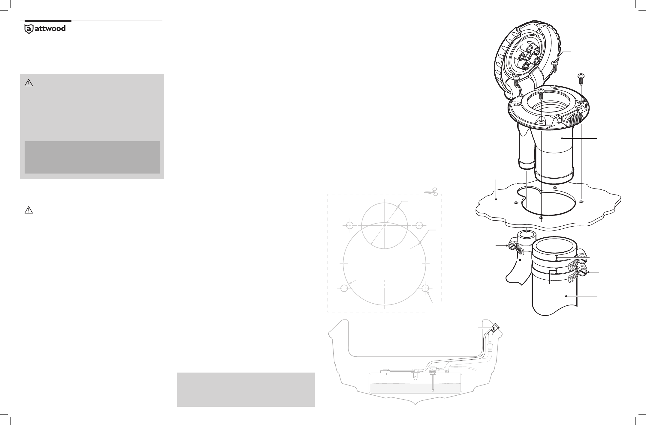
FIGURE 2
FIGURE 1 - MOUNTING TEMPLATE
Cut out and orient to match final position of Deck Fill
2-1/4" dia.
57mm
1-1/4" dia.
32mm
Drill for (4)
#8 Screws
Fill Hose
Vent Hose
Deck
Stainless Steel Screws
#8 pan head fasteners appropriate
for specific deck material
(not included)
FIGURE 3
Full Pressure Relief System
Deck Fill
©2011 Attwood Corporation
1016 North Monroe Lowell, MI 49331
www.attwoodmarine.com
Deck Fill
Do not install
straight Deck
Fill on a vertical
surface.
DO NOT USE
Template may not be to scale.
Refer to separate template sheet
included in product carton.
1/4" Max
6mm
1/4" Max
6mm
Clamps (2)
(not included)
Clamp
(not included)