Mux output option ph0 ph1 – Achronix Speedster22i Memory PHY User Manual
Page 19
UG043, April 26, 2014
19
Mux Output Option
Ph0
Ph1
9
180
202.5
10
202.5
225
11
225
247.5
12
247.5
270
13
270
292.5
14
292.5
315
15
315
337.5
16
337.5
360
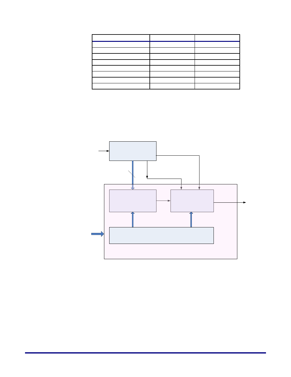
In the second stage the phase interpolator mixes the two phases (ph0 and ph1) mentioned
above to meet the required delay/phase difference. For example, to push out the incoming
signal by a 100 degree phase, the first stage selects phase 90 and phase 112.5, and then the
second stage uses this pair and fine tunes it to meet the required 100 degree push out. Figure
12 below provides a block diagram of the SDLL and Phase Interpolator.
Slave DLL
Course selection of clocks
Through Muxs
Fine Selection through
Programmable drive
strength
Phase Interpolator Block per clock
Pbias
Nbias
Bias from MDLL
Decoder
LSB[3:0]
MSB[16:0]
Phase
Interpolator
Codes<5:0>
Phase
Interpolator
Clock out
17
Figure 12: SDLL and Phase Interpolator Block Diagram