Configuration modes and pins – Achronix Speedster22i Configuration User Manual
Page 8
8
UG033, December 18, 2013
Configuration Modes and Pins
Speedster22iHD devices have four configuration modes: CPU, Serial Flash x1, Serial Flash x4
and JTAG. The selection between the first 3 is done by tying CONFIG_MODESEL pins to the
values shown in Table 3. The fourth configuration mode, which is JTAG, is independent of
the mode pins and can be enabled by setting the appropriate bits in the User Data Register of
the JTAG TAP Controller. Once JTAG mode is enabled, it overrides all other configuration
modes until disabled.
Table 3: Configuration Modes and CONFIG_MODESEL Settings
Configuration Mode
CONFIG_MODESEL[2:0]
CPU
100
Serial x1 Flash
001
Serial x4 Flash
010
JTAG
Always active
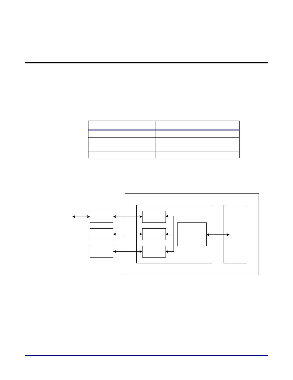
Figure 2 below shows a simplified block diagram view of the different configuration
interfaces connecting up to the Speedster22iHD FPGA.
Configuration Logic
User
Logic
Speedster22iHD FPGA
JTAG
Interface
Configuration
Manager
SPI Flash
Controller
CPU Slave
Controller
JTAG
Cable
Serial (SPI)
Flash
External
CPU
USB
JTAG
Serial Data
Figure 2: Configuration Interface Connections to the Speedster22iHD FPGA