Serial x1 flash – Achronix Speedster22i Configuration User Manual
Page 10
10
UG033, December 18, 2013
In Figure 4 above:
1. After CONFIG_RSTN is deasserted, CPU_CLK needs to continue being clocked to
ensure that the FPGA cycles through the FCU states and the configuration memory is
cleared. At that point, CONFIG_STATUS is released and is pulled high.
2. Some time after CONFIG_STATUS is pulled high, CSN should be pulled low to
begin writing the bitstream data into the FPGA. When the last set of data is written
into the FPGA, CSN is pulled high.
3. Once CSN is pulled high, CPU_CLK needs to continue being clocked for a total of
about 12,000 clock cycles. After 9,000 clock cycles, CONFIG_DONE should be
asserted to indicate that configuration has completed, and the remaining 3,000 clock
cycles are needed to ensure that the FCU can successfully transition into user mode.
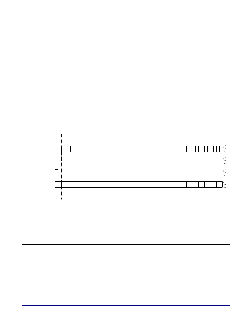
The waveform in Figure 5 depicts the window of a sample valid bitstream programming
section of the configuration.
CPU_CLK
CSN
DQ[7:0]
CONFIG_STATUS
AA
55
AA
55
20
20
16
41
00
00
00
00
00
00
00
00
00
38
00
01
00
00
00
07
11
15
00
Sync
ID Code
NOP
NOP
Write Cmd
Write Data
Figure 5: Sample Valid Bitstream Programming
Serial x1 Flash
The Serial Flash programming mode allows flash memories to be used to configure the
Speedster22iHD FPGA. In this mode the FPGA is the master, and therefore supplies the clock
to the Flash memory.
Figure 6 below provides a block diagram of how a serial flash can be connected to a
Speedster22iHD FPGA in x1 mode.