Configuration pins and clock selection – Achronix Speedster22i Configuration User Manual
Page 14
14
UG033, December 18, 2013
Configuration Pins and Clock Selection
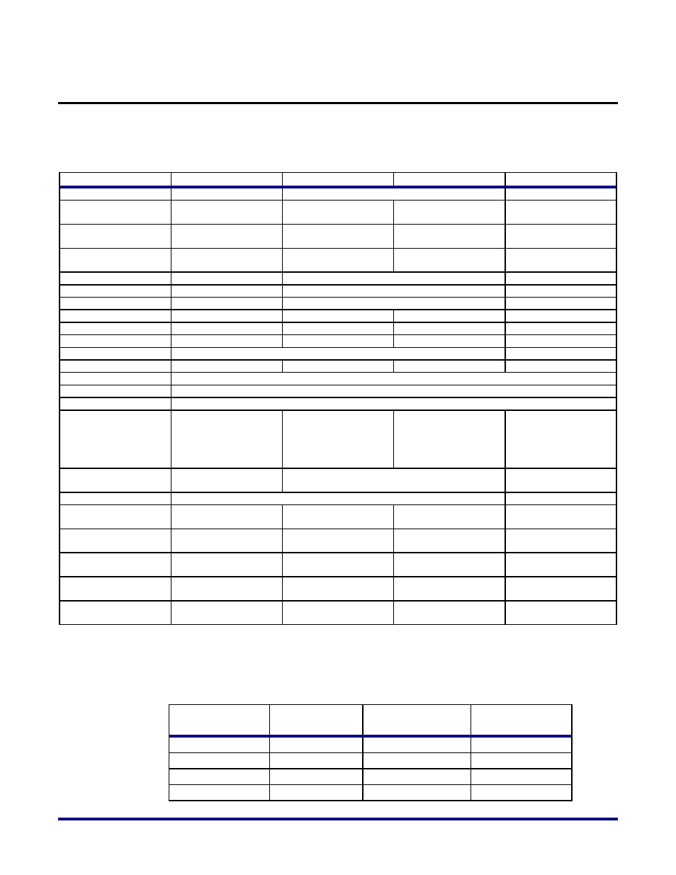
Table 4 below lists the names and functions of all of the configuration and JTAG pins used in
the four different configuration modes.
Table 4: Configuration/JTAG Pins and Functions
External Pin Name
CPU
Serial Flash x1
Serial Flash x4
JTAG
SDI
DQ[0]
Serial data output to flash memory
-
SDO[3]
DQ[1]
Input of configuration
data from flash
-
SDO[2]
DQ[2]
Input of configuration
data from flash
-
SDO[1]
DQ[3]
Input of configuration
data from flash
-
SDO[0]
DQ[4]
Input of configuration data from flash
-
SCK
-
Flash clock output
-
HOLDN
DQ[5]
Hold output to flash
-
CSN[3]
DQ[6]
Active-low chip select
-
CSN[2]
DQ[7]
Active-low chip select
-
CSN[1]
-
Active-low chip select
-
CSN[0]
Active-low chip select
-
CPU_CLK
CPU clock
-
-
-
CONFIG_RSTN
Active-low configuration reset
CONFIG_DONE
Open-drain configuration done output
CONFIG_STATUS
Open-drain SRAM initialization complete output
CONFIG_MODESEL
[2:0]
Config mode select.
Set to '100'.
Config mode select.
Set to '001'.
Config mode select.
Set to '010'.
Config mode select.
Not used in JTAG
mode, but these pins
should be set to '100',
'001', '010' or '000'.
CONFIG_SYSCLK_
BYPASS
Bypass config system
clock. Tie to '0' or '1'.
Bypass config system clock. Set to '0'.
Bypass config system
clock. Tie to '0' or '1'.
CONFIG_CLKSEL
Selects configuration clock. Set to '0'.
Tie to '0' or '1'
TDI
-
-
-
Input of config data
from JTAG controller
TDO
-
-
-
Serial data output to
JTAG controller
TMS
-
-
-
Mode select from
JTAG controller
TRSTN
-
-
-
Active-low reset from
JTAG controller
TCK
-
-
-
Clock from JTAG
controller
Table 5 highlights the different clock sources that can be selected in the various configuration
modes, and Figure 10 illustrates the same FPGA configuration clock selection logic.
Table 5: Clock Sources for Configuration Modes and Settings
CONFIG_SYS_CLK
_BYPASS
CONFIG_CLKSEL
CONFIG_MODESEL
[2:0]
FCU CLK
0
0
001, 010
On-chip oscillator
1
0
001, 010
CPU_CLK
0/1
0
100
CPU_CLK
0
1
000, 001, 010, 100
TCK