3 virtual ports, 1 creating virtual ports, Virtual ports -7 – Cabletron Systems 6500 User Manual
Page 85: Creating virtual ports -7, Figure 6-1, Terminating pvps -7
SmartSwitch 6500 User Guide 6-7
Virtual Ports and Static Connections
Virtual Ports
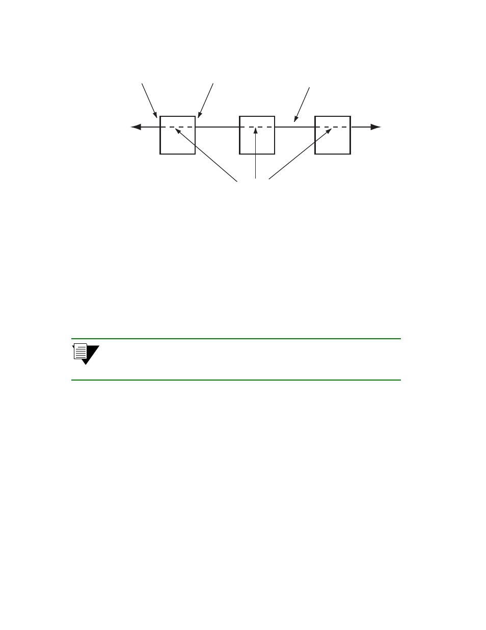
Figure 6-1 Terminating PVPs
6.3
VIRTUAL PORTS
The SmartSwitch 6500 supports the ability to create virtual ports. Typically, virtual ports are used for terminating
Permanent Virtual Path (PVP) connections. Virtual ports are designated by the following convention:
number of the physical port + a period + virtual port number
For example,
7a1.3
,
3a4.7
,
5b2.1
, and so on.
Note
Zero (0) cannot be used as a a virtual port value. Virtual port zero (0) is reserved,
and represents the physical port. For example, 7a1.0 and 5b2.0 represent the
physical ports 7a1 and 5b2, and are not available for designating virtual ports.
6.3.1
Creating Virtual Ports
Virtual ports are created on physical ports by first allocating a range of Virtual Path Identifiers (VPIs), and then
distributing the VPIs among the virtual ports. The number of VPIs used depends on the number of virtual ports needed
and the range of VPIs controlled by each virtual port.
When creating virtual ports, it’s important to remember that the virtual port number represents the Base VPI used by
the virtual port. For example, the virtual port
5b1.3
uses Base VPI = 3.
Creating virtual ports on the SmartSwitch 6500 consists of the following basic process
•
Create a traffic descriptor for the virtual port that meets its bandwidth and service category
requirements.
PVP
Switch 1
PVP
Switch 2
PVP
Switch 3
1
5
5
3
3
2
VPI
VPI
PVPs Internal
to the switch
Physical Link
To VPI = 1
or virtual port
XyZ.1
T
o VPI = 2
or virtual port
XyZ.2