3 installing the csm, Installing the csm -7, Figure 2-4 – Cabletron Systems 6500 User Manual
Page 27: Close the ejectors. the installation is complete
SmartSwitch 6500 User Guide 2-7
Switch Installation and Setup
Switch Installation and Assembly
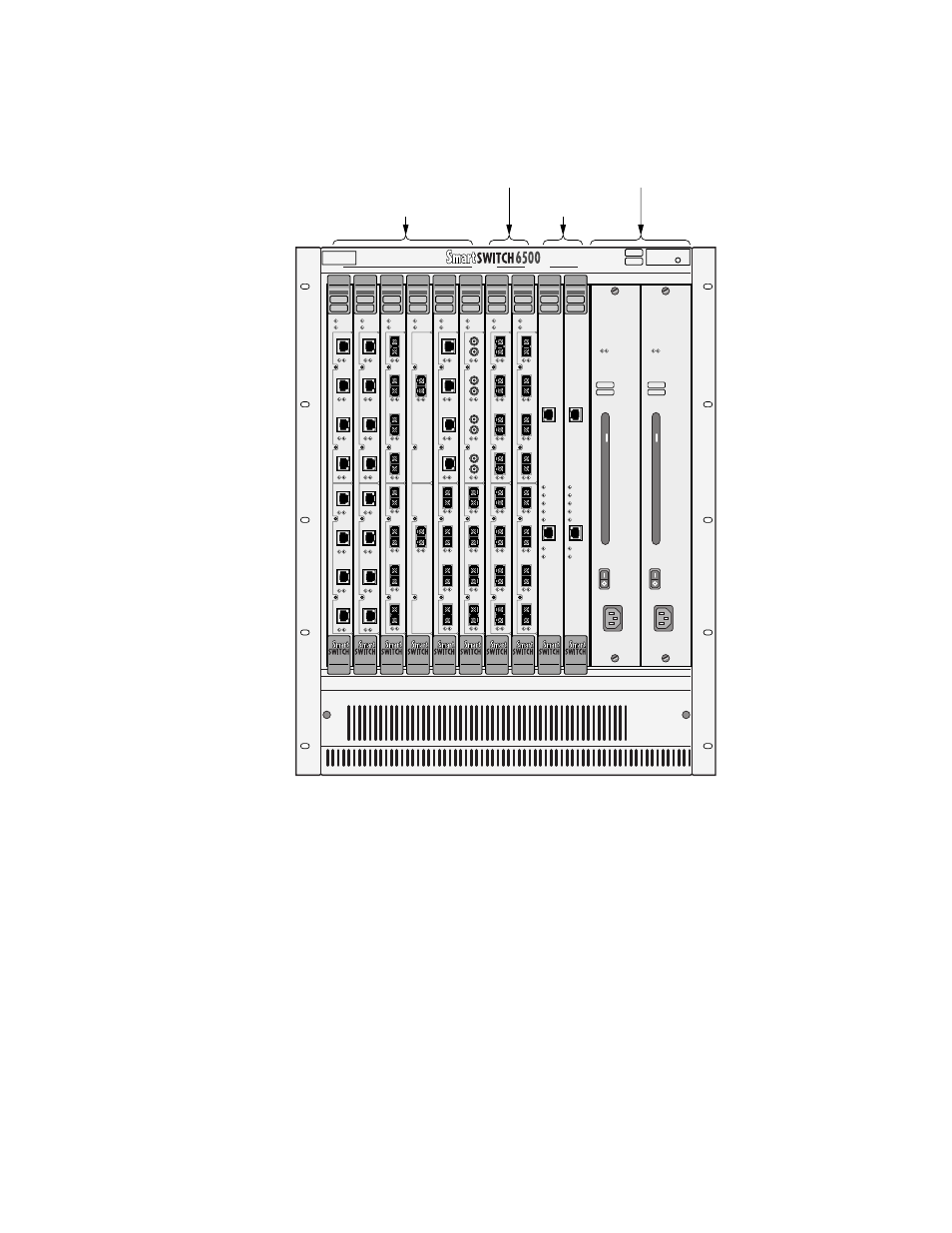
Figure 2-4 Module placement in the SmartSwitch 6500 chassis
2.2.3
Installing the CSM
Follow these instructions to install the CSM module into the chassis.
1.
Remove the metal blank that covers either slot 9 or slot 10 of the chassis (CSMs can reside only in
slots 9 and 10). See the legend on the top edge of the SmartSwitch 6500 chassis.
2.
Open the ejectors at the top and bottom of the CSM module.
3.
With the ejector labeled
6A-CSM512
at the top, align the top and bottom of the CSM module with
the tracks in the slot (see Figure 2-5).
4.
Slide the CSM module into the chassis. The CSM module obscures the view of the tracks at the
bottom of the chassis, so be sure to look at that area as you begin to slide the module into the chassis.
5.
Close the ejectors. The installation is complete.
A
FAIL /MODE
FAIL/ OK
ATM
CPU
TSM
NO SYNC
D
ATA
123
4
6A-IOM-29-4-IR
NO SYNC
D
ATA
123
4
6A-IOM-21-4
B
FAIL /MODE
FAIL/ OK
ATM
CPU
TSM
NO SYNC
D
ATA
123
4
6A-IOM-29-4-IR
B
FAIL /MODE
FAIL/ OK
ATM
CPU
TSM
NO SYNC
D
ATA
123
4
6A-IOM-21-4
B
FAIL /MODE
FAIL/ OK
ATM
CPU
TSM
NO SYNC
D
ATA
1
6A-IOM-31-1
NO SYNC
D
ATA
2
6A-IOM-31-1
B
FAIL /MODE
FAIL/ OK
ATM
CPU
TSM
NO SYNC
D
ATA
123
4
6A-IOM-21-4
NO SYNC
D
ATA
123
4
6A-IOM-29-4-IR
B
ATM
FAIL /MODE
CPU
FAIL/ OK
TSM
NO SYNC
D
ATA
123
4
6A-IOM-21-4
NO SYNC
D
ATA
123
4
6A-IOM-21-4
B
ATM
COM
ENET
POWER
ACTIVE
STANDBY
FAIL
ENET RDY
TX DATA
RX DATA
ATM
COM
ENET
POWER
ACTIVE
STANDBY
FAIL
ENET RDY
TX DATA
RX DATA
NO SYNC
D
ATA
1234
6A-IOM-22-4
FAIL /MODE
FAIL/ OK
ATM
CPU
TSM
NO SYNC
D
ATA
1234
6A-IOM-22-4
NO SYNC
1234
6A-IOM-22-4
FAIL /MODE
FAIL/ OK
ATM
CPU
TSM
NO SYNC
D
ATA
1234
6A-IOM-22-4
NO SYNC
1234
6A-IOM-22-4
NO SYNC
D
ATA
123
4
6A-IOM-67-4
PS1
PS2
CSM
TSM/CPU
TSM
10
9
8
7
6
5
4
3
2
1
TSM
(Without CPU) or
Other Modules
Slots 1 – 6
TSM
With CPU
Slots 7 & 8
Power
Supplies
CSM
Slots 9 & 10
REDUNDANCY
PWR
100 - 125V - 8.0A
200 - 250V - 4.0A
50/60 Hz
REDUNDANCY
PWR
100 - 125V - 8.0A
200 - 250V - 4.0A
50/60 Hz