Figure 5-3 – Cabletron Systems 6500 User Manual
Page 77
SmartSwitch 6500 User Guide 5-7
Routing
IP Routing
•
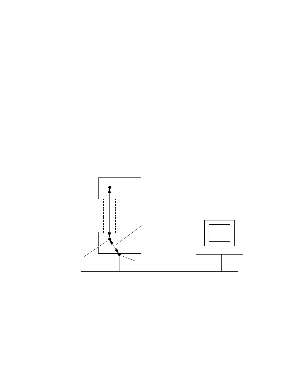
SW2 is connected to SW1 through PNNI, and both switches are part of the same emulated LAN.
To reach SW2 with the Ethernet-based NMS, create an IP route that assigns SW1's switch client as SW2's default
gateway to the network 128.205.99.0. Enter the following on SW2 (see Figure 5-3):
Smart6500 # add route
DestNetIP() : 128.205.99.0
< address of the Ethernet network to reach
GatewayIP() : 90.1.1.254
< IP address of SW1's LANE client
Smart6500 #
Switch SW2 can now communicate with the NMS on the Ethernet network.
To see the route, enter the
show route
command on SW2
Smart6500 # show route
ROUTE NET TABLE
destination gateway flags Refcnt Use Interface
------------------------------------------------------------------------
0.0.0.0 0.0.0.0 1 0 0 zn0
90.1.1.0 90.1.1.33 1 0 1688 zn1
128.205.99.0 90.1.1.254 1 3 5660 ei0
------------------------------------------------------------------------
ROUTE HOST TABLE
destination gateway flags Refcnt Use Interface
------------------------------------------------------------------------
127.0.0.1 127.0.0.1 5 0 0 lo0
------------------------------------------------------------------------
Smart6500 #
Figure 5-3 IP routing through SW1 for connectivity to the Ethernet network
NMS
Ethernet network 128.205.99.0
SW1
SW2
AT
M
L
in
k
ELAN
Switch client
on SW2, 90.1.1.33
Switch client
on SW1,
IP Rou
te
Ethernet interface
90.1.1.254
128.205.99.254
Switch client on SW1 is
defined as SW2’s
gateway to the Ethernet