Figure 1 mounting the heater (continued), Installation at corner, Figure 2 – Qmark RCC - Cove Heaters User Manual
Page 2: Figure 3, Figure 4
2
4” (102 mm) MIN. (DRY WALL CEILINGS)
6” (152 mm) MIN. (LAY IN OR VINYL
CEILINGS OR PLASTIC MOLDING)
1“ (25.4 mm) MIN. BETWEEN BOTTOM
OF HEATER AND ANY FABRIC
6‘ MINIMUM
(1.83 m)
CLEARANCE
TO FLOOR
C
U
R
T
A
IN
S
CEILING
W
A
L
L
FLOOR
MOUNTING RESTRICTIONS
}
4” (102 mm)(DRY WALL CEILINGS)
6” (152 mm) LAY IN OR VINYL CEILINGS
OR PLASTIC MOLDING)
BACK VIEW
MOUNTING SLOTS
MOUNTING BRACKETS
34” TO 132”
(0.86 M to 3.35 M)
CEILING
WALL
3”
2”
TOP VIEW
4-3/16“ (106.4 mm)
1-1/2” (38.1 mm)
HEATERS TO BE MOUNTED
AT LEAST SIX (6) FEET
(1.83 M) FROM THE FLOOR.
MINIMUM CLEARANCES:
• 4” (102 mm) MIN. TO DRY WALL CEILING.
• 6” (152 mm) MIN. TO LAY-IN OR VINYL CEILING
OR PLASTIC MOLDING.
CEILING
2-1/2”
13/16”
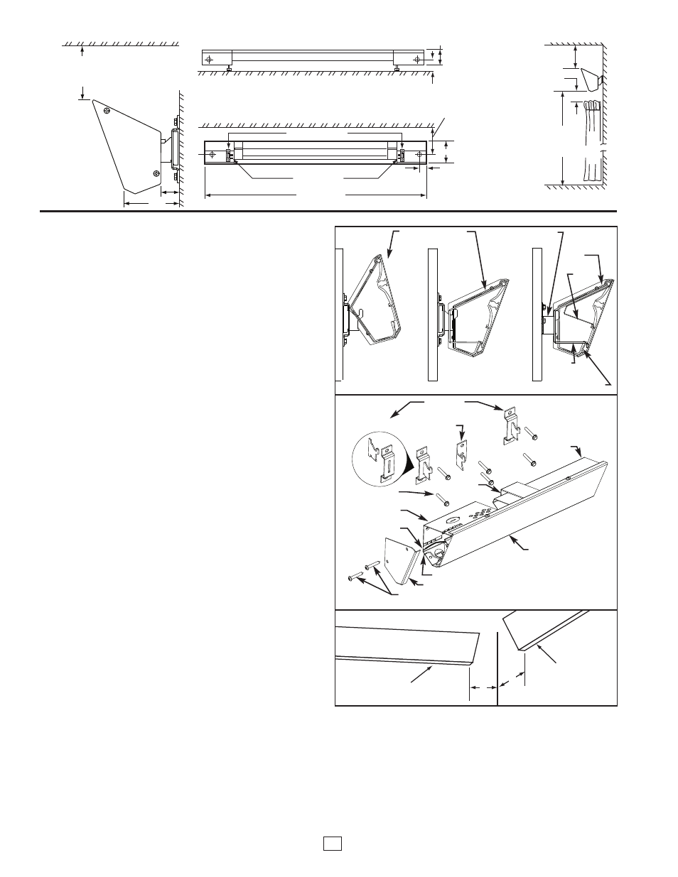
Figure 1
MOUNTING THE HEATER (Continued)
4.
To mount cove heater, attach center support bracket to the center
wall bracket by tilting the heater back and allowing the upper slot
to fall onto the bracket hook per Figure 2. Attach the junction
boxes to the end wall brackets in a similar manor. Bring the cove
heater forward to lock into place.
For 1500 to 1800 Watt Heaters:
The 1500 & 1800 watt cove heaters require the additional support of
(2) center wall brackets due to the extra length. The mounting steps
are similar to the 450 to 1200 watt cove heater with the following
exceptions:
1.
After the approximate center location between the end wall brack-
ets has been determined, measure 30 inches (762 mm) on each
side of this location to determine the approximate location to
mount the center wall brackets. Locate a stud nearest each mark.
Use these studs for the center wall bracket locations. (Disregard
original 30 inch location marks)
2.
Using the provided template, align the top of the template with the
ceiling and the center of the pre-punched holes with the bracket
marks on the wall. Choosing the proper bracket location holes,
mark the bracket pilot hole locations using the selected pre-
punched holes provided on the template. With the fasteners pro-
vided, mount the assembled end wall brackets and center wall
brackets to the wall. Measure the distance between the center
(slot) of the left end wall bracket and the hook of the left center
wall bracket. Add 3-5/8 inches (92 mm) to this (left end) value and
record it for the left center support bracket location on the cove
heater. Determine the distance between the center of the right
end wall bracket and the hook of the right center wall bracket.
Add 3-5/8 inches (92 mm) to this (right end) value and record it
for the right center support bracket placement on the cove heater.
3.
Orient the cove heater face down on a protective flat surface.
Using the left end value recorded in step 2, measure this distance
from the left end of the cove heater and mark this location on the
back surface of the panel. Using the right end value recorded in
step 2, measure this distance from the right end of the cove
heater and mark this location on the back surface of the panel.
Slide the center support brackets to the marked positions on the
panel, aligning the center of the brackets with each mark.
4.
To mount cove heater, attach center support brackets to the cen-
ter wall brackets by tilting the heater back and allowing the upper
slot to fall onto the bracket hook per Figure 2. Attach the junction
boxes to the end wall brackets in a similar manor. Bring the cove
heater forward to lock into place.
5.
The cove heater can be wired from either end of the heater.
Install a cable clamp (supplied by others) in one of the knockouts
located in back of the junction boxes you plan to use. Insert the
power supply cable through the cable clamp allowing approxi-
mately 6” (152mm) of cable length to remain inside the box to
facilitate wiring. Add at least 2 inches of cable loop between wall
and knockout entering the junction box to allow for heater expan-
sion.
6.
Refer to wiring diagrams on next page.
7.
Attach end caps (found in parts bag) as shown in Figure 3.
INSTALLATION AT CORNER
1.
Heaters must be located so that the ends of each heater are
4 inches (102 mm) from side wall. See Figure 4.
Figure 2
CUTAWAY SHOWING
CENTER MOUNTING
BRACKET DETAILS
TOP
FLANGE
BACK
WRAP
WIREWAY
CENTER
SUPPORT
BRACKET
MOUNTING HEATER
TO END BRACKET
ASSEMBLY
ALIGN JUNCTION
BOX SLOT WITH
BRACKET HOOK
HEATER LOCKED IN
POSITION ON END
WALL BRACKET
Figure 3
END WALL
BRACKET ASSEMBLY
BACK WRAP
HEAT SHIELD
CENTER
SUPPORT
BRACKET
#10-16 X 1-1/2”
LONG SCREWS
JUNCTIONBOX
ELEMENT LEAD
CROSSOVER LEAD
END CAP
#8-18 X 1” LONG SCREWS
COVE HEATER
FRONT PANEL
CENTER WALL
BRACKET
HEATER
HEATER
4”
4”
Figure 4