Qmark CUS900 - Stock Cabinet Unit Heater User Manual
Page 8
8
WIRING
SEE WARNING STEPS 1, 2 & 3 ON PAGE 1 OF THIS
INSTRUCTION SHEET.
1.
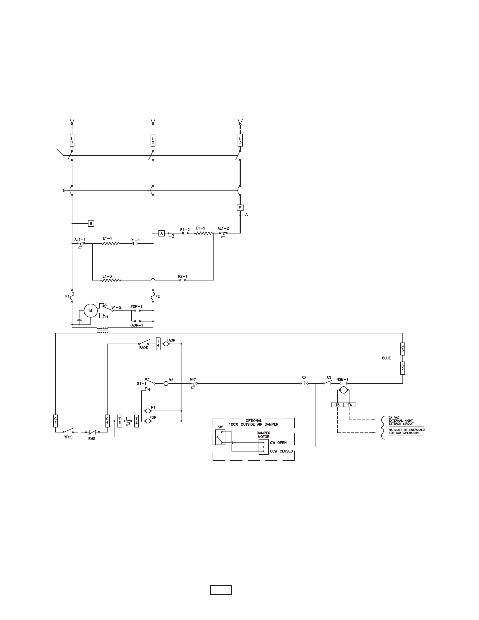
Figure 4 shows a typical wiring diagram.
2.
For actual wiring, see the diagram located on the inside of the
front cover.
3.
All field wiring must be 75˚ C min.
TO CONVERT 208, 240, 480 & 600 VOLT
STOCK 5 & 10 KW HEATERS
From Three Phase To Single Phase
1.
Remove front cover.
2.
Refer to wiring diagram located located inside
front cover.
NOTE: Terminal block and wires that need to be
changed are located in wire way above right
hand (RH) blower housing.
3.
Remove two screws holding wireway cover to fan
panel.
4.
Rotate wireway cover up and out to remove.
5.
Terminal block is located within wireway.
6.
Relocate wires per wiring diagram located inside
front cover.
7.
Reinstall wireway cover and reinstall screws.
8.
Reinstall front cover.
Typical Wiring Diagram
See wiring diagram on the inside of heater front cover.
SUPPLY
POWER
OPTIONAL DISCONNECT SWITCH
OPTIONAL CIRCUIT BREAKER
ORANGE
EMS=ENERGY MANAGEMENT SYSTEM TIE-IN (CONTACTS MUST BE CLOSED FOR DAY OPERATION)
RFHS=REMOTE MOUNTED FAN/HEAT ON-OFF SWITCH (FIELD SUPPLIED)
NOTE: IF EMS AND/OR RFHS ARE INSTALLED REMOVE ORANGE WIRE BETWEEN C1 AND C4.
FOR EXTERNAL CONTROL SUPPLY:
1. REMOVE BLUE JUMPER BETWEEN C2 AND C3.
2. CONNECT EXTERNAL CONTROL (24 VAC STANDARD, 120 VAC OPTIONAL) TO C1 AND C2.
S1 = FAN/HEAT HIGH-LOW SELECTOR SWITCH
S2 = DOOR INTERLOCK SWITCH
S3 = FAN/HEAT ON-OFF SWITCH (FACTORY INSTALLED OPTION)
NSB = NIGHT SETBACK RELAY (FACTORY INSTALLED OPTION)
AL = AUTO RESET LIMIT
MR = MANUAL RESET LIMIT (FACTORY INSTALLED OPTION)
T = BUILT-IN OR REMOTE MOUNTED SINGLE POLE THERMOSTAT
FAOS = FAN AUTO-ON SWITCH (BUILT-IN = FACTORY INSTALLED OPTION)
(REMOTE MOUNTED = FIELD INSTALLED OPTION)
FDR = FAN DELAY RELAY
FAOR = FAN AUTO-ON RELAY (FACTORY INSTALLED OPTION)
1609-2081-020