Qmark LFK Series - Wall Heater User Manual
Page 3
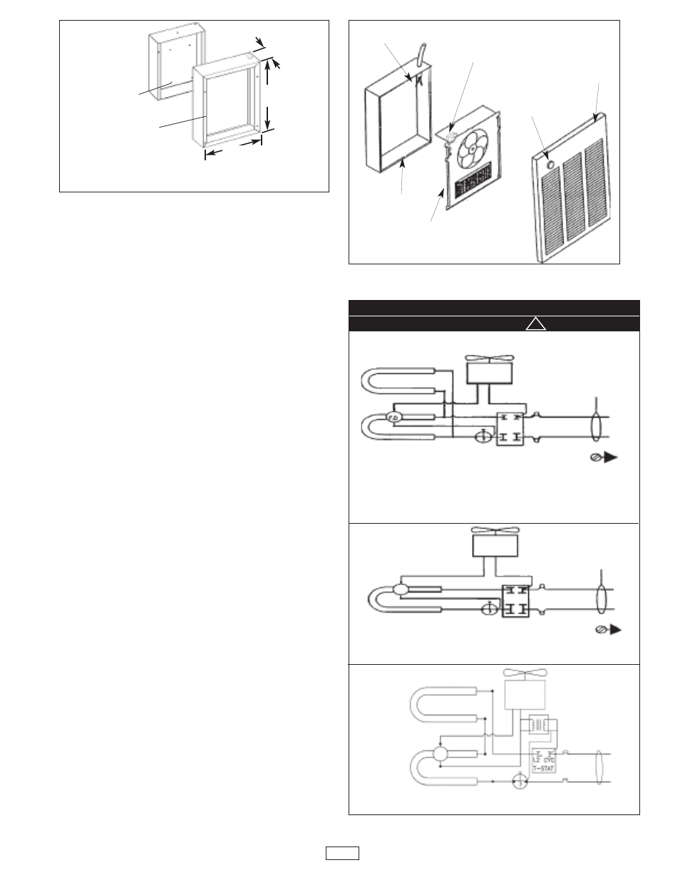
Installation of Back Box With Optional
Surface-Mounting Frame (See Figure 3).
1. Secure back box to wall (with knockouts in upper right
hand corner) using screws and anchors.
2. Hang the surface-mounting frame on the back box.
Ensure that the back edge of the surface-mounting
frame is flush against the wall.
NOTE: If heater is located in a high traffic area where it may
be subjected to vandalism or abuse, take extreme care to see
that the back box is firmly attached to the wall.
3. Power Supply Wiring
NOTE: Wiring Compartment Volume - 119in3 (1950cm3).
a. Run a power supply cable into the area of the upper
right corner of the mounting frame.
NOTE: If the wiring is to run through the wall, cut a hole in the
area of the top of the back box. Run the supply wire through
this hole. Then remove the knockout from the top of the box
and proceed to step c.
b. Remove the knockout on the top side of the frame.
c. Feed the power supply cable through the frame allow-
ing 6" (152mm) of lead to remain inside the frame
d. Secure the power supply cable to the back box
(using cable clamps, connector, or other suitable strain
relief) allowing 6”(152mm) of lead to remain inside the
back box.
e. Ground the back box by connecting the supply ground
leadwire to the green ground screw located in the
inside top of the back box.
Installation of Heater Assembly and Grille
After back box is competely installed and no further con-
struction dirt is expected, clean debris from back box, remove
heater assembly from its carton, then refer to Figure 4 and
proceed as follows:
1. Insert the heater assembly into back box, placing
the four mounting holes (with key-hole slots) over the
screws in the back box. Tighten all screws securely.
2. If surface-mounting frame is used, ensure that the
frame is even with all four heater assembly tabs before
tightening screws.
3. Connect the power lead wires (field wiring) to the lead
wires from the heater assembly. See wiring diagram
in next column.
4. Turn thermostat to the extreme counterclockwise
position.
5. Mount the grille using four (4) long screws provided.
The screws thread into holes located in the side
flanges of the back box.
6. Push thermostat knob onto thermostat shaft.
Fig. 3: Surface Mounting Installation
Fig. 4
HANG FRAME
ON BACK BOX
15-5/32"
(385mm)
19"
(482mm)
3-13/16"
(97mm)
MOUNT BACK BOX TO
WALL USING REAR
MOUNTING HOLES.
3
POWER
LEADS
RECESS BACK
BOX
HEATER
ASSEMBLY
THERMOSTAT
KNOB
GRILLE
1500, 4800, 4000, & 3000 WATT HEATERS
120V, 208V, 240V, OR 277V (Full wattage heaters can be converted to half
wattage by removing the red jumper wire connecting the top and bottom element ter-
minals.)
NOTE: Conversion not applicable on K151.
4800, 4000, & 3000 WATT HEATERS
347V, 600V
2000 & 1500 WATT HEATERS
208V, 240V, OR 277V
WIRING DIAGRAMS (SINGLE PHASE)
Element
Element
Element
Element
Element
Red
Fan Motor
TʼStat
GND
GND
F.D.
F.D.
Manual
Reset
Limit
Manual
Reset
Limit
Manual
Reset
Limit
Field
Wiring
Fan Motor
TʼStat
Field
Wiring
Fan Motor
!
CAUTION
To assure proper operation of fan, thermostat must not cycle fan
on and off. Follow wiring diagram exactly.