Important caution warning – Qmark LFK Series - Wall Heater User Manual
Page 2
Installation of Recessed Back Box
in New Construction
1. Mounting Back Box (See Figure 1).
a. Place the back box between two 16" (406mm)
center-to-center wall studs at the desired mounting
height but no closer than 8" (203mm) to adjacent wall
or floor.
Note: If wall studs are spaced greater than 16” on center,
additional framing supports may be necessary.
b. Align back box such that the bottom and sides will be
flush with finished wall surface (top flange of back box
should protrude approximately 1/2" (13mm) from fin-
ished wall surface).
c. Secure the back box in position with wood screws or
nails as shown in Figure 1.
2. Power Supply Wiring (See Figure 1).
NOTE: Wire Compartment Volume - 119in3 (1950cm3).
a. Run a power supply cable into the knockout area in
the upper right hand corner of the back box. Refer to
Figure 1.
b. Install a cable clamp in the “knockout” in the top of
the back box.
c. Insert power supply cable through cable clamp, allow-
ing at least 6" (152mm) of leads to extend inside the
back box.
d. Ground the back box by connecting the supply ground
leadwire to the green ground screw located in the
inside top of the back box.
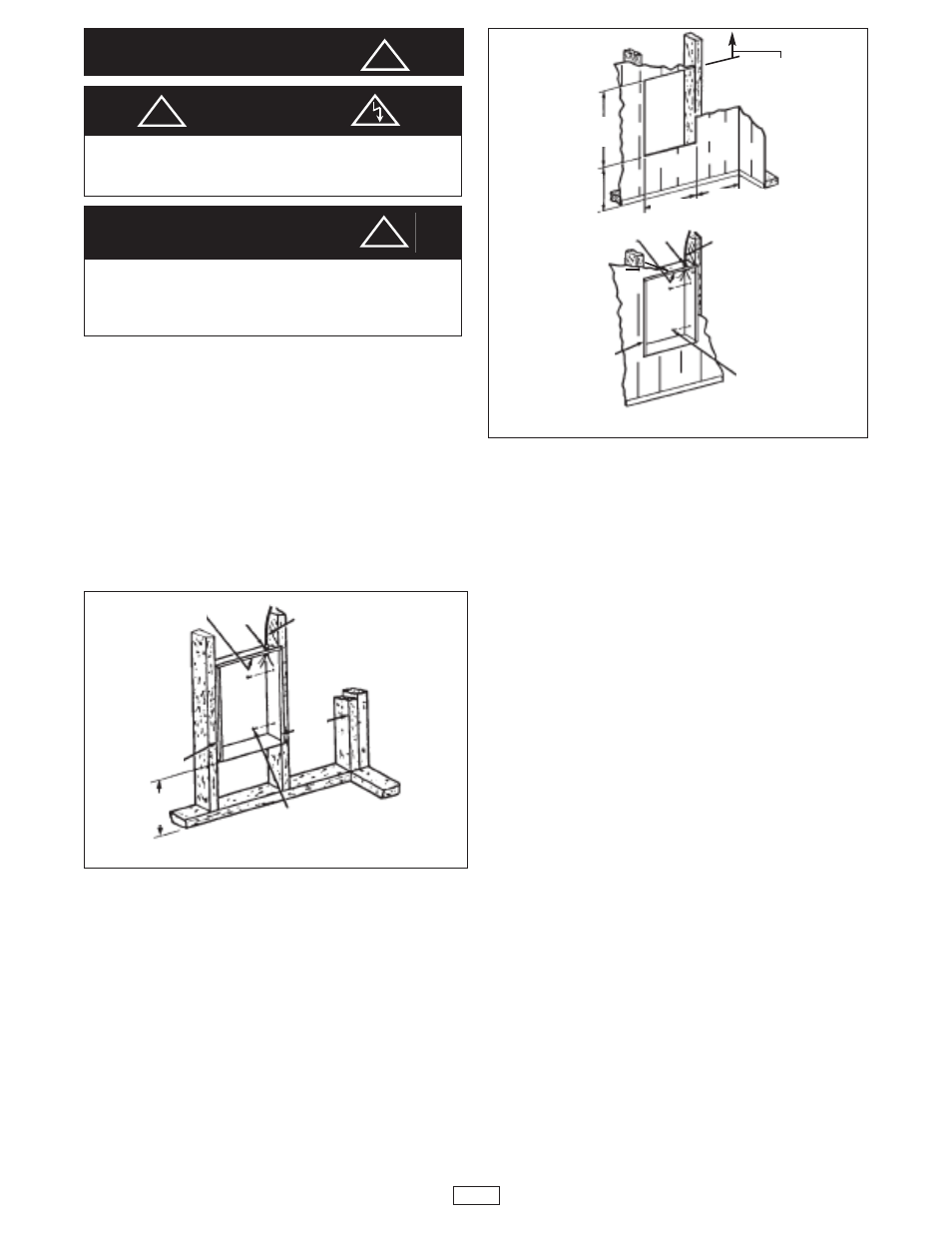
Installation of Recessed
Back box in Exisiting Construction
1. Provide a wall opening 14-1/2" (362mm)wide x 18-1/2"
(470mm) high at the desired mounting height, but no
closer than 8" (203mm) to any adjacent wall or floor and
36” (915mm) to ceiling. (See Figure 2.)
NOTE: Locate so at least one side of the opening is at stud.
2. Power Supply Wiring
NOTE: (Wiring Compartment Volume - 119in3 (1950cm3).
a. Run a power supply cable into the area above the top
of the wall opening.
b. Install a cable clamp in the knockout in the top of
back box.
c. Insert power supply cable through cable clamp, allow-
ing at least 6" (152mm) of cable length to remain
inside the back box to facilitate connections.
d. Ground the back box by connecting the supply ground
leadwire to the green ground screw located in the
inside top of the back box.
3. Mounting Back Box
a. Place the back box into wall opening flush with fin-
ished wall surface on bottom and sides of box. (Top
flange of back box should protrude approximately 1/2"
(13mm) from finished wall surface).
b. Secure the back box in place with wood screws or nails.
NOTE: For correct wire sizing, please refer to the
National Electrical Code, Section 310. Only use copper
wire rated at least 75° C Do not use alluminum wire with
this unit.
IMPORTANT
CAUTION
WARNING
DO NOT INSTALL HEATER UPSIDE DOWN OR SIDE-
WAYS.
DO NOT USE HEATER WITHOUT GRILLE.
FOR WALL MOUNTING ONLY. DO NOT INSTALL HEATER
CLOSER THAN 8" (203 mm) TO THE FLOOR OR ANY
ADJACENT WALL SURFACE. DO NOT INSTALL CLOSER
THAN 36" (915 mm) TO THE CEILING.
Fig. 1: Locating Recessed Back Box in New Construction
Fig. 2: Locating Recessed Back Box in Existing Construction
!
!
!
2
GROUND
SCREW
BACK BOX
BACK BOX
CABLE
CLAMP
8” MIN.
(203mm)
8” MIN.
(203mm)
8” MIN.
(203mm)
18-1/2” MIN.
(470mm)
MIN. 36” (915mm)
to ceiling
14-1/2” MIN.
(362mm)
NAIL OR SCREW
(2 EACH SIDE)
GROUND SCREW
CABLE CLAMP
NAIL OR SCREW
(2 EACH SIDE)
8” MIN.
(203mm)
POWER SUPPLY CABLE
POWER SUPPLY CABLE