Wiring operation – Qmark ICG - Explosion Proof Convectors User Manual
Page 3
3
WIRING
OPERATION
WARNING:
Hazard of Shock. Any installation involving electric
heaters must be effectively grounded in accordance with the
National Electrical Code.
1. All wiring must be done in accordance with local codes and
the National Electrical Code by a qualified person as
defined in the NEC.
WARNING:
Use copper conductors only.
2. Rough-in-line-wiring to unit in manner approved for haz-
ardous locations. (See warning below.)
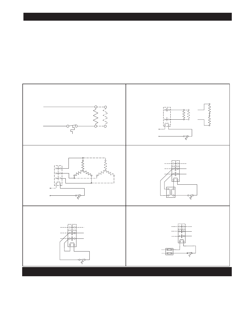
3. Wire per diagrams 1 through 6 based on the rating and con-
trol options listed in table 2. Refer to table 3 for amperage
specifications.
4. Remove cover of conduit box for connections. Use either
opening and plug the other with the plug provided.
5. In single phase units (except 480 V) the heaters must be
wired in parallel, combining L1 to L1, L2 to L2 and for 3
phase unit, L3 to L3. On 480V single phase units the ele-
ments must be wired in series.
6. Re-assemble cover with a minimum of 7 turns.
WARNING:
(Group B atmospheres) To prevent ignition of
Group B atmospheres, conduit runs must not exceed 3/4” in
size and all conduit runs 1/2” size and larger must have a seal-
ing fitting connected within 2”, 6” or 18” of the terminal enclo-
sure depending on the exact model. For correct placement,
refer to data located on the enclosure label.
Elements
Optional Thermostat
Built-In or Ext. Supplied
Single Phase — No Controls, 120-277V
& Heater Amps < 22A
Diagram 1
Diagram 3
Diagram 5
Diagram 2
Diagram 4
Diagram 6
Elements
Optional Thermostat
Built-In or Ext. Supplied
Single Phase — No Controls, Volts > 277V
& 120–277V When Heater Amps > 22A
External
Contactor
480V 1PH
Double
Element
Heaters
Control
Voltage
Elements
Optional Thermostat
Built-In or Ext. Supplied
External
Contactor
Control
Voltage
Three Phase – No Controls
Optional Thermostat
Built-In or Ext. Supplied
Contactor
Transformer
Element Wiring
1 PH or 3 PH
Single or Double
Element
Single or Three Phase
With Controls — Contactor & Transformer
Optional Thermostat
Built-In or Ext. Supplied
Contactor
Line
Voltage
Control
Voltage
Element Wiring
1 PH or 3 PH
Single or Double
Element
Single or Three Phase
With Controls — Contactor & Line Voltage Control
Optional Thermostat
Built-In or Ext. Supplied
Contactor
Element Wiring
1 PH or 3 PH
Single or Double
Element
Single or Three Phase With Controls —
Contactor & External Supplied Control Voltage
Terminal
Block
External
Supplied
Control
Voltage
CAUTION: Users should install adequate controls and safety
devices with their electric heating equipment. Where the conse-
quences of failure may be severe, back-up controls are essen-
tial. The safety of the installation is the responsibility of the
user.
1. Do not operate heater at voltages in excess of that stamped
on the heater since excess voltage will shorten heater life
and cause high element temperatures which may exceed
allowable temperatures of operation in a hazardous
atmosphere.
L2 or N
L1
L2
L1
L2
L2
L3
L1
L1
L2
L3
L1
L2
L3
L1
L2
L3
L1
or N