Installation – Qmark ICG - Explosion Proof Convectors User Manual
Page 2
2
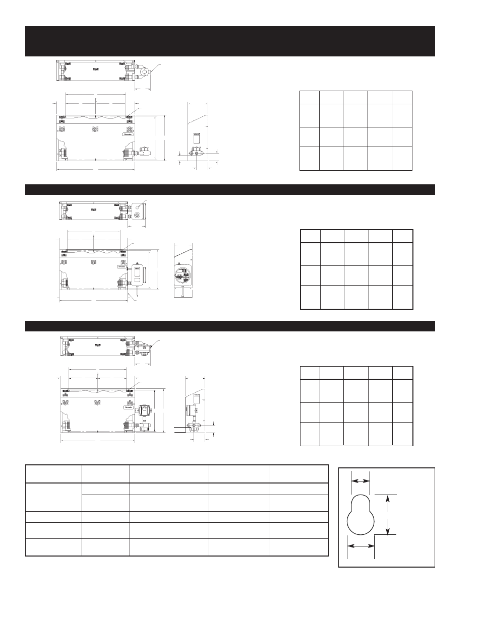
INSTALLATION
kW
A
B
C
D
1.6
1.8
34
20
7
3.6
3.2
58
32
16
13
7.6
4.0
4.5
70
48
24
11
9.0
N/A
Dimensions (In.)
G SERIES MODELS WITHOUT CONTROLS — GROUPS B, C AND D
Dimensions (In.)
G SERIES MODELS WITH BUILT-IN CONTROLS — GROUPS B, C AND D
Dimensions (In.)
G SERIES MODELS WITH THERMOSTAT ONLY — GROUPS C AND D
Type of Mounting
** Accessory
Screw Size to Fit
Surface
Hardware
Screw Type
Drill Size and Type
Mtg Hole Size
Concrete Block
Ackerman
Rd. Hd. Mach. Steel
1/2” Masonry
† 1/4” x 20 x ............lg
Masonry
Lead Anchor
Rd. Hd. Mach Steel or Pan Hd.
5/16” Masonry
† # 1/4” x .................lg
Metal (Self Tapping)
Wood Studs
— —
Wood or Metal (Self Tapping)
— —
† # 1/4” x .................lg
Plaster wall Hollow or
— —
Toggle Bolt
#7 Twist
† # 1/4” x .................lg
Similar Type
* Metal Beam,
Nuts
Rd. Hd. Mach. Steel
#7 Twist
† 1/4” x 20 x ............lg
Channel, etc.
Washers
Table 1 — Suggested Heater Mounting Screws — Types and Sizes
*If clearance permits use washer, lock washer and nut; otherwise drill and tap to these lengths, add thickness of beam, washers, nut, etc.
**If mounting structure permits. Except plastered hollow walls explosive type anchors can be used. Suggested size noted in Table and/or
sketches should be used to determine size of anchors.
†Select overall length of screw to provide a minimum penetration of 1 inch into base wall material.
1/2
7/8
5/16
Mounting Hole
Detail “A”
Figure 1A
Figure 1B
Figure 1C
kW
A
B
C
D
1.6
1.8
34
20
7
3.6
3.2
58
32
16
13
7.6
4.0
4.5
72
48
24
11
9.0
N/A
kW
A
B
C
D
1.6
1.8
34
20
7
3.6
3.2
58
32
16
13
7.6
4.0
4.5
70
48
24
11
9.0
N/A
7/8
3/4" Conduit Entrance
7
D
See Detail "A"
8-15/16
D
C
C
B
19
20-1/16
A
2-3/8
5-1/16
3-3/8
1" Conduit Entrance
8-7/8
D
See Detail "A"
C
C
D
19 20-1/16
8-15/16
A
B
Feet are Optional
Primarily Used to Protect
Thermowell During Shipping
and Installation
3/4" Conduit Entrance
7
D
See Detai "A"
C
C
D
19
20-1/16
8-15/16
5-1/16
3-3/8
A
2-3/8