Warning, Caution – Qmark FDI - Floor Drop-In Heaters User Manual
Page 2
GENERAL INSTRUCTIONS
When installing the heater(s) as draft barriers below windows it is
recommended that the heater(s) capacity be matched to the heat
loss of the glass area. Also, the heat spread of each heater is
about 5 feet (1524mm) so for continuous draft control heaters
should be mounted 5 feet (1524mm) apart.
When using the heater(s) as the sole source of heat in the room,
the capacity of the heater(s) should match the heat loss of the
room. For good room temperature control, a Marley wall thermo-
stat mounted on an inside wall is recommended.
To prevent discoloration of some synthetic drapery materials and
to avoid undue wall discoloration, the side of the heater should be
at least 1inch (25,4mm) from the drapes nearest fold and the end
of the heater should be no closer than 3 feet (914mm) to the wall
(See specifications and Warning No. 6).
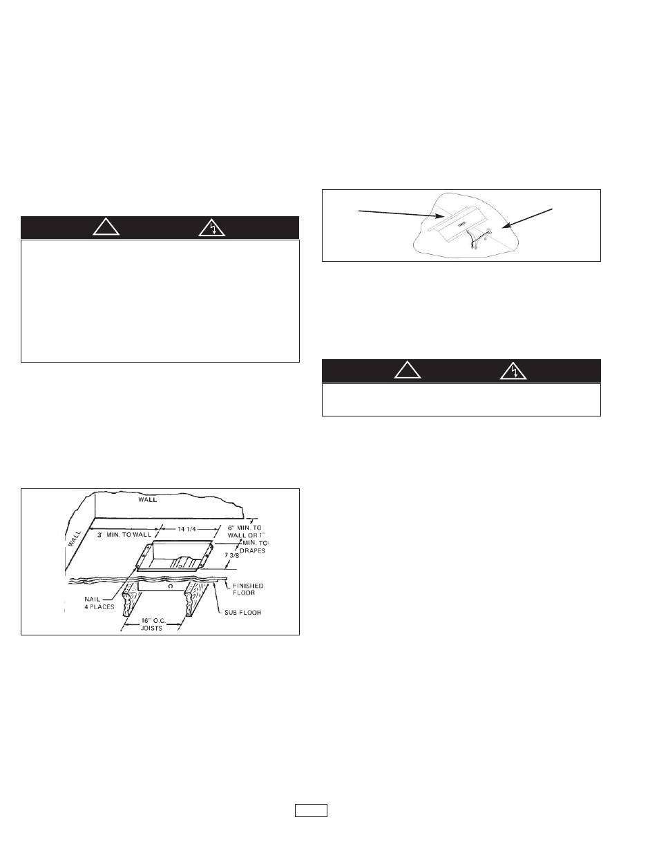
ENCLOSURE INSTALLATION IN WOOD FLOORS
1. Provide a hole 7-3/8” by 14-1/4” (187mm by 362mm) in floor
at least 6” (152mm) from the wall with the longest side par-
allel to the wall as shown in Figure 1.
2. Insert the enclosure into the opening and secure with four
nails.
NOTE: Enclosure may be installed with flanges flat against the
floor and the floor covering between the grille and enclosure
flange,provided the floor covering is no thicker than 3/4”
(19,1mm) and is trimmed to prevent any portion of it from extend-
ing past the flange and into the enclosure.
WIRING NOTICE
This heater is NOT provided with built-in power disconnect
switch. To comply with the 1993 National Electrical Code (Section
424-19 and 424-20) the following options are available:
1. The room thermostat used to control this heater must be
either a double pole, positive off design that will de-energize
all ungrounded conductors when in the “Off” position, or
2. The main disconnect service panel must be located within
sight of the heater, or
3. The disconnecting means must be able to be locked in the
open position.
WIRING THE ENCLOSURE
(See Warning No. 2)
1. Bring supply wire into desired knockout, leaving 6” (152mm)
of leads extending into the enclosure as shown in Figure 2.
NOTE: Wiring compartment volume - 15in
3
(244cm
3
)
2. Secure the ground lead to the ground screw on the bottom of
the enclosure.
3. For Model I1500, connect the white (neutral) supply lead to
the white receptacle lead and the black line supply lead to
the black receptacle lead as shown in Figure 2. (See also
wiring diagram shown in Figure 4). For I1504 connect the
two black supply leads to the two black receptacle leads.
(See wiring diagram shown in Figure 4.)
4. Install junction box cover as shown in Figure 2.
TO REDUCE WATTAGE
The heater wattage may be reduced from 1500W to 750W by
removal of two (2) red jumpers.
HEATER ASSEMBLY INSTALLATION
NOTE: For units with built-in thermostat, the temperature sens-
ing bulb must be located on the side of the heater closest to the
wall for most efficient operation.
Slide heater assembly into the enclosure part way so the plug can
be inserted into receptacle in junction box cover. After plug is fully
inserted into receptacle, push heater down in position and secure
with two (2) screws provided. (See Figure 3)
GRILLE INSTALLATION
1. If a floor covering is installed after the enclosure is installed,
make certain it does not extend past the edges of the enclo-
sure. (See “Enclosure Installation In Wood Floors” Note ).
2. Place the grille over the enclosure and secure with the two
painted screws provided as shown in Figure 3. (See Warning
No. 7).
2
YOUR HEATER IS PROVIDED WITH AN ALARM (BUZZER OR
WARNING LIGHT) THAT WILL SOUND OR ILLUMINATE IF THE
HEATER IS OVERHEATING FOR ANY REASON. IF THIS OCCURS,
TURN DOWN THE THERMOSTAT UNTIL THE ALARM STOPS AND
ALLOW THE HEATER TO COOL FOR AT LEAST 30 MINUTES.
CHECK TO MAKE SURE THE AIR FLOW THROUGH THE HEATER IS
NOT BLOCKED (SEE WARNING 5 AND 6 ON PAGE 1) AND THEN
TURN THE THERMOSTAT BACK TO THE DESIRED TEMPERATURE.
IF THE ALARM CONTINUES TO CYCLE, DISCONTINUE USING
HEATER, TURN OFF THE POWER TO THE HEATER AT THE CIR-
CUIT BREAKER PANEL AND HAVE THE HEATER CHECKED BY A
QUALIFIED SERVICE PERSON.
WARNING
!
TO PREVENT A POSSIBLE ELECTRIC SHOCK, BE SURE POWER
TO HEATER IS OFF AT MAIN DISCONNECT PANEL BEFORE
INSERTING HEATER INTO ENCLOSURE.
CAUTION
!
Figure 1
Figure 2
Wall
Ground terminal in
receptacle closest
to wall