Dell D/Dock Expansion-Station User Manual
Page 4
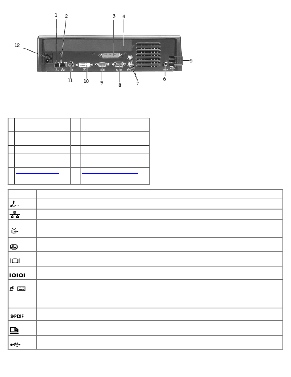
The following table shows the connectors and icons on the back of the expansion station and indicates the purpose of each
connector.
1
7
2
8
3
9
4 PCI expansion-card
cover
10
5
(3) 11
6
12 AC power connector
Connector Description
RJ-11 modem connector —
Connects a telephone line.
RJ-45 network connector —
Connects a network interface cable.
S-video TV-out connector —
Connects to any device (such as a television, VCR, or camcorder) that accepts
S-video input.
digital-video interface connector —
Connects an external display.
video connector —
Connects an external VGA monitor.
serial connector —
Connects a serial device, such as a serial mouse.
PS/2 connectors (2) —
Connects PS/2-compatible devices, such as a mouse, keyboard, or external numeric
keypad. Shut down the computer before attaching or removing a PS/2-compatible device. If the device does
not work, install the device drivers from the floppy disk or CD that came with the device, and restart the
computer. You can use the integrated keyboard and an external keyboard at the same time. When you attach a
PS/2 keyboard or PS/2 numeric keypad, the integrated keypad is disabled.
S/PDIF connector —
Connects a digital audio (S/PDIF) cable.
parallel connector —
Connects a parallel device, such as a parallel printer.
USB 2.0 connectors —
Connects up to three USB 2.0-compliant devices to the back of the expansion station.
A fourth USB connector can be found on the left side of the expansion station.