Carrier AQUAZONE 50RTP03-20 User Manual
Page 8
8
Step 4 — Mount the Unit —
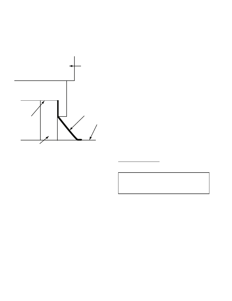
For proper operation,
units must be mounted on a roof curb as shown in Fig. 5. Roof
curn dimensional data is shown in Fig. 4. Follow these guide-
lines when installing the roof curb:
1. Set unit on curb.
2. Align unit so that its return and supply air direction match
the return and supply air opening in the roof curb frame.
3. Run both the return and supply loop piping, as well as the
electrical supply line, through the pipe chase provided in
the curb.
Step 5 — Install Condensate Drain
1. Install a condensate trap at each unit with the top of
the trap positioned below the unit condensate drain
connection.
2. Design the length of the trap (water seal) based on the
amount of positive or negative pressure on the drain pan.
As a rule, 1 in. of trap is required for each inch of nega-
tive pressure on the unit.
Note that condensate is allowed to drain onto the roof.
Step 6 — Make Piping Connections —
Depend-
ing on the application, there are 3 types of WSHP piping sys-
tems to choose from: water loop, ground-water and ground
loop. Refer to Piping Section of Carrier System Design Manual
for additional information.
All WSHP units use low temperature soldered female pipe
thread fittings for water connections to prevent annealing and
out-of-round leak problems which are typically associated with
high temperature brazed connections. Refer to Table 1 for con-
nection sizes. When making piping connections, consider the
following:
• Use a backup wrench when making screw connections to
unit to prevent internal damage to piping.
• Insulation may be required on piping to avoid condensa-
tion in the case where fluid in loop piping operates at
temperatures below dew point of adjacent air.
• Piping systems that contain steel pipes or fittings may
be subject to galvanic corrosion. Dielectric fittings may
be used to isolate the steel parts of the system to avoid
galvanic corrosion.
WATER LOOP APPLICATIONS — Water loop applications
usually include a number of units plumbed to a common pip-
ing system. Maintenance to any of these units can introduce air
into the piping system. Therefore, air elimination equipment
comprises a major portion of the mechanical room plumbing.
The flow rate is usually set between 2.25 and 3 gpm per ton
of cooling capacity. For proper maintenance and servicing,
pressure-temperature (P/T) ports are necessary for temperature
and flow verification.
In addition to complying with any applicable codes, consid-
er the following for system piping:
• Piping systems utilizing water temperatures below
50 F require
1
/
2
-in. closed cell insulation on all piping
surfaces to eliminate condensation.
• All plastic to metal threaded fittings should be avoided
due to the potential to leak. Use a flange fitted substitute.
• Teflon tape thread sealant is recommended to minimize
internal fouling of the heat exchanger.
• Use backup wrench. Do not overtighten connections.
• Route piping to avoid service access areas to unit.
• The piping system should be flushed prior to operation to
remove dirt and foreign materials from the system.
GROUND-WATER APPLICATIONS — In addition to com-
plying with any applicable codes, consider the following for
system piping:
• Install shut-off valves for servicing.
• Install pressure-temperature plugs to measure flow and
temperature.
• Boiler drains and other valves should be connected using
a “T” connector to allow acid flushing for the heat
exchanger.
• Do not overtighten connections.
• Route piping to avoid service access areas to unit.
• Use PVC SCH80 or copper piping material.
NOTE: PVC SCH40 should not be used due to system high
pressure and temperature extremes.
Water Supply and Quantity — Check water supply. Water
supply should be plentiful and of good quality. See Table 2 for
water quality guidelines.
In all applications, the quality of the water circulated
through the heat exchanger must fall within the ranges listed in
the Water Quality Guidelines table. Consult a local water treat-
ment firm, independent testing facility, or local water authority
for specific recommendations to maintain water quality within
the published limits.
GROUND-LOOP APPLICATIONS — Temperatures between
25 to 110 F and a cooling capacity of 2.25 to 3 gpm of flow per
ton is recommended. In addition to complying with any appli-
cable codes, consider the following for system piping:
• Piping materials should be limited to only polyethylene
fusion in the buried sections of the loop.
• Galvanized or steel fittings should not be used at any
time due to corrosion.
• All plastic to metal threaded fittings should be avoided
due to the potential to leak. Use a flange fitted substitute.
• Do not overtighten connections.
• Route piping to avoid service access areas to unit.
• Pressure-temperature (P/T) plugs should be used to mea-
sure flow of pressure drop.
FLASHING
ROOF
CURB
GASKET
50 RTP
UNIT
Fig. 5 — 50RTP Curb Installation
IMPORTANT: Failure to comply with the above required
water quality and quantity limitations and the closed-
system application design requirements may cause damage
to the tube-in-tube heat exchanger that is not the responsi-
bility of the manufacturer.