Carrier AQUAZONE 50RTP03-20 User Manual
Page 24
24
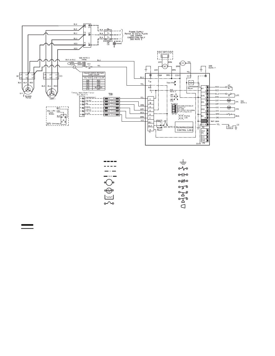
Complete C
BC
— Blower Contactor
CB
— Circuit Breaker
CC
— Compressor Contactor
CO
— Sensor, Condensate Overflow
ECR
— Enthalpy Control Relay
FP1
— Sensor, Water Coil Freeze Protection
FP2
— Sensor, Air Coil Freeze Protection
GFI
— Ground Fault Interrupter
HP
— High-Pressure Switch
JW3
— Clippable Field Selection Jumper
LAR
— Low Ambient Relay
LOC
— Loss of Charge Pressure Switch
MAS
— Mixed Air Sensor
OAT
— Outdoor Air Thermostat
PDB
— Power Distribution Block
RVS
— Reversing Valve Solenoid
TB
— Terminal Block
TRANS — Transformer
Factory Line Voltage Wiring
Factory Low Voltage Wiring
NOTES:
1. Compressor and blower motor thermally protected internally.
2. All wiring to the unit must comply with NEC (National Electrical
Code) and local codes.
3. 208/230-v transformers will be connected for 208-v operation. For
230-v operation, disconnect RED lead at L1, and attach ORG
lead to L1. Close open end of RED lead.
4. FPI thermistor provides freeze protection for WATER. When using
ANTIFREEZE solutions, cut JW3 jumper.
5. Typical heat pump thermostat wiring shown. Refer to thermostat
installation instructions for wiring to the unit. Thermostat wiring
must be “Class 1” and voltage rating equal to or greater than unit
supply voltage.
6. Factory cut JW1 jumper and dry contact will be available between
AL1 and AL2.
7. Transformer secondary ground via Complete C board standoffs
and screws to control box. (Ground available from top two stand-
offs as shown.)
LEGEND
Field Line Voltage Wiring
Field Low Voltage Wiring
Printed Circuit Trace
Optional Wiring
Relay/Contactor Coil
Thermistor
Condensate Pan
Circuit Breaker
Ground
Solenoid Coil
Relay Contacts - N.O.
Relay Contacts - N.C.
Temperature Switch
Switch - Low Pressure
Switch - High Pressure
Wire Nut
Fig. 6 — 50RTP03-06 Units — Typical Control Wiring with Complete C Control
a50-8553