Carrier AQUAZONE 50RTP03-20 User Manual
Page 46
46
Clean condensers with an inhibited hydrochloric acid solu-
tion. The acid can stain hands and clothing, damage concrete,
and, without inhibitor, damage steel. Cover surroundings to
guard against splashing. Vapors from vent pipe are not harmful,
but take care to prevent liquid from being carried over by the
gases.
Warm solution acts faster, but cold solution is just as effec-
tive if applied for a longer period.
GRAVITY FLOW METHOD — Do not add solution faster
than vent can exhaust the generated gases.
When condenser is full, allow solution to remain overnight,
then drain condenser and flush with clean water. Follow acid
manufacturer’s instructions. See Fig. 23.
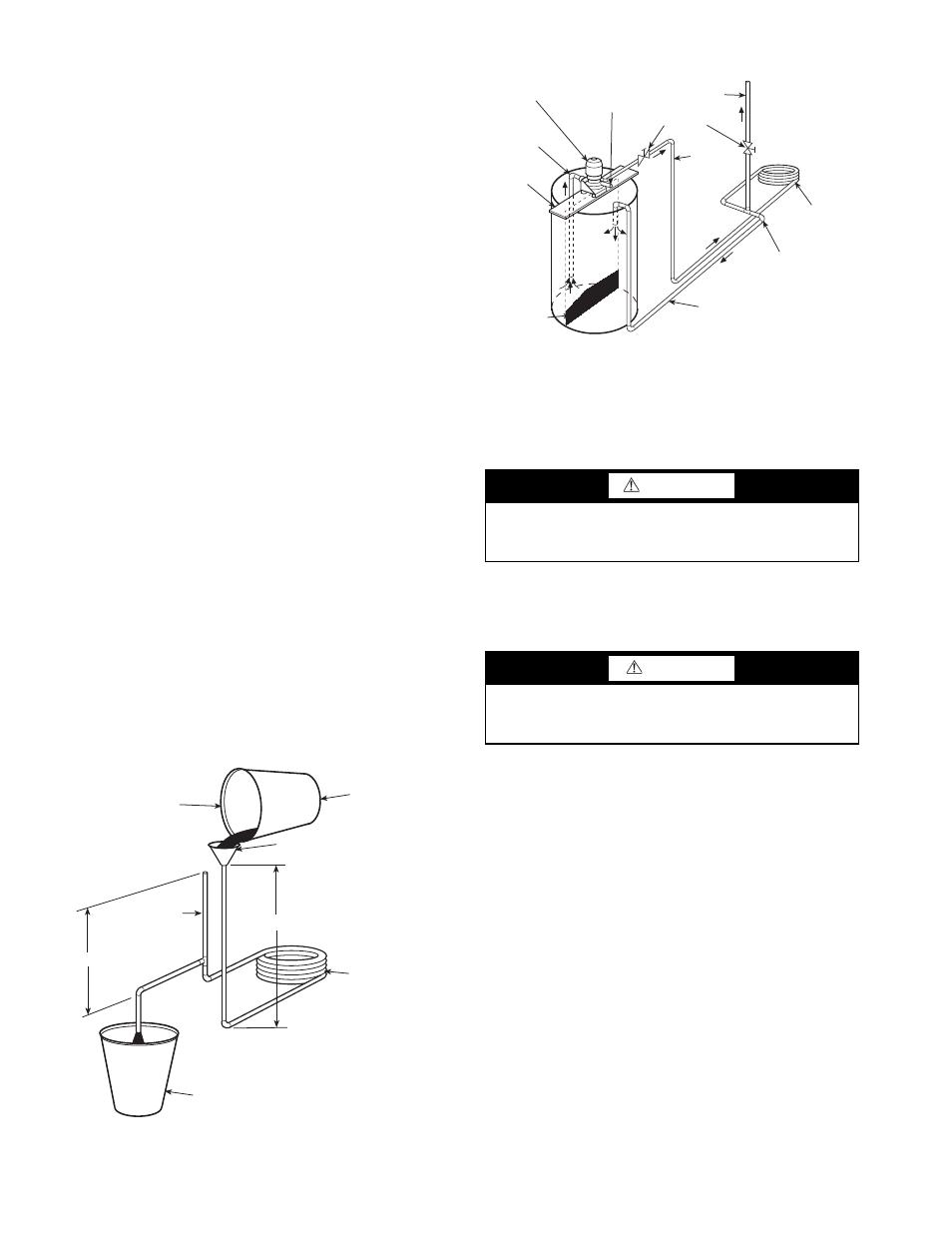
FORCED CIRCULATION METHOD — Fully open vent
pipe when filling condenser. The vent may be closed when
condenser is full and pump is operating. See Fig. 24.
Regulate flow to condenser with a supply line valve. If
pump is a nonoverloading type, the valve may be fully closed
while pump is running.
For average scale deposit, allow solution to remain in con-
denser overnight. For heavy scale deposit, allow 24 hours.
Drain condenser and flush with clean water. Follow acid manu-
facturer’s instructions.
Checking System Charge —
Units are shipped with
full operating charge. If recharging is necessary:
1. Insert thermometer bulb in insulating rubber sleeve on
liquid line near filter drier. Use a digital thermometer for
all temperature measurements. DO NOT use a mercury
or dial-type thermometer.
2. Connect pressure gage to discharge line near compressor.
3. After unit conditions have stabilized, read head pressure
on discharge line gage.
NOTE: Operate unit a minimum of 15 minutes before
checking charge.
4. From standard field-supplied Pressure-Temperature chart
for R-410A, find equivalent saturated condensing
temperature.
5. Read liquid line temperature on thermometer; then
subtract from saturated condensing temperature. The dif-
ference equals subcooling temperature.
6. ADD refrigerant to raise the temperature or REMOVE
refrigerant (using standard practices) to lower the temper-
ature (allow a tolerance of ± 3° F), as required.
Refrigerant Charging
NOTE: Do not vent or depressurize unit refrigerant to atmo-
sphere. Remove and recover refrigerant following accepted
practices.
Air Coil Fan Motor Removal
Motor power wires need to be disconnected from motor
terminals before motor is removed from unit.
1. Shut off unit main power supply.
2. Loosen bolts on mounting bracket so that fan belt can be
removed.
3. Loosen and remove the 2 motor mounting bracket bolts
on left side of bracket.
4. Slide motor/bracket assembly to extreme right and lift out
through space between fan scroll and side frame. Rest
motor on a high platform such as a step ladder. Do not
allow motor to hang by its power wires.
Replacing the WSHP Open Controller’s Bat-
tery —
The WSHP Open controller’s 10-year lithium
CR2032 battery provides a minimum of 10,000 hours of data
retention during power outages.
NOTE: Power must be ON to the WSHP Open controller
when replacing the battery, or the date, time and trend data will
be lost.
1. Remove the battery from the controller, making note of
the battery's polarity.
2. Insert the new battery, matching the battery's polarity
with the polarity indicated on the WSHP Open controller.
FILL CONDENSER WITH
CLEANING SOLUTION. DO
NOT ADD SOLUTION
MORE RAPIDLY THAN
VENT CAN EXHAUST
GASES CAUSED BY
CHEMICAL ACTION.
PAIL
FUNNEL
CONDENSER
PAIL
3’ TO 4’
VENT
PIPE
5’ APPROX
1”
PIPE
Fig. 23 — Gravity Flow Method
WARNING
To prevent personal injury, wear safety glasses and gloves
when handling refrigerant. Do not overcharge system —
this can cause compressor flooding.
CAUTION
Before attempting to remove fan motors or motor mounts,
place a piece of plywood over evaporator coils to prevent
coil damage.
SUCTION
PUMP
SUPPORT
TANK
FINE MESH
SCREEN
RETURN
GAS VENT
PUMP
PRIMING
CONN.
GLOBE
VALVES
SUPPLY
1” PIPE
CONDENSER
REMOVE WATER
REGULATING VALVE
Fig. 24 — Forced Circulation Method