2 frequency measurement, 1 the adaptive trigger level – Dynalco SWT-2000 Speed Switch/Speed Transmitter User Manual
Page 29
Operating Instructions SWT-2000
DYNALCO
25
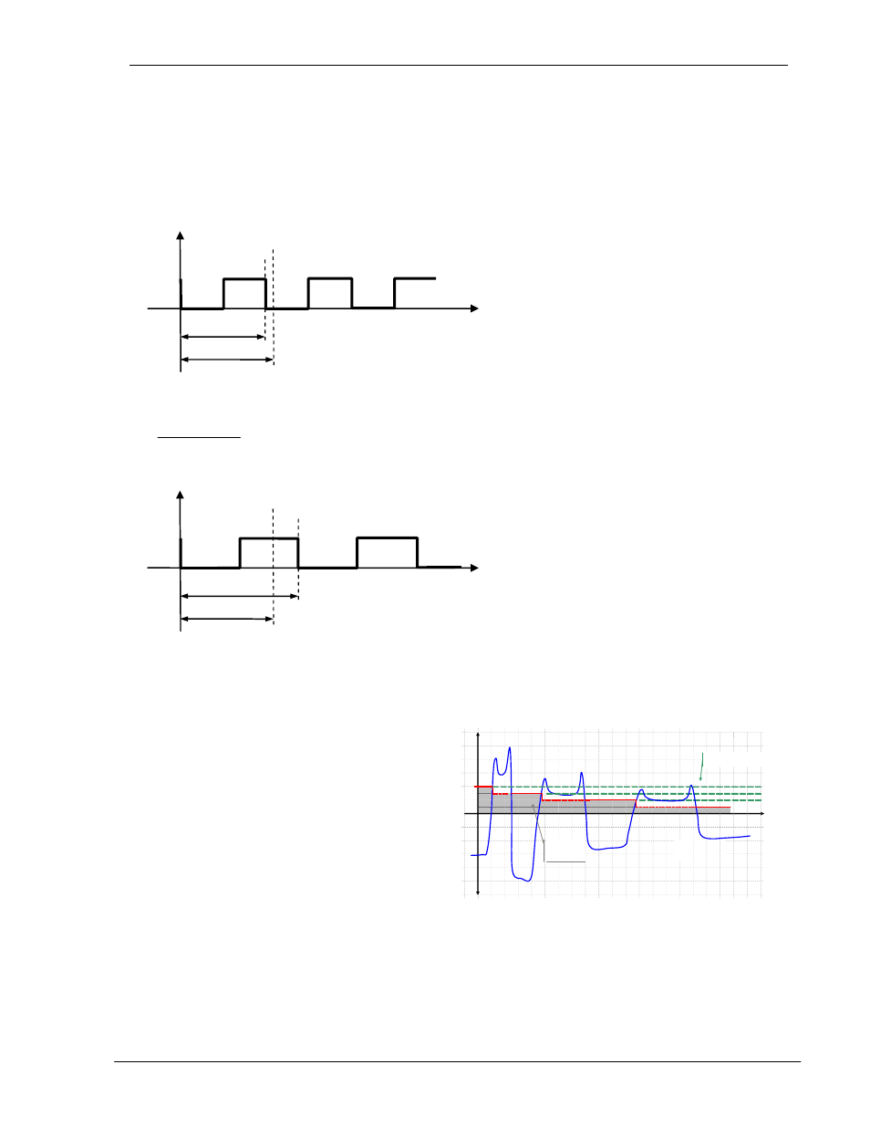
7.2 Frequency Measurement
Every frequency measurement starts with the negative edge of the input signal. The last measured edge prior
the end of the measurement interval completes the running measurement and immediately starts the next.
An optimum measurement is achieved when the input period is shorter than the measurement interval.
Input signal
Input period
Measurement
End of the measurement interval
Time
If the input period is greater than the measurement interval, the frequency is calculated as follows:
n
t
f
×
=
t
Measuremen
1
n: Number of measurement intervals without input signal
This continues until a second negative edge arrives.
Input signal
Input period
Measurement
End of the measurement interval
Time
The calculation and adjustment of outputs occurs immediately after the start of the next measurement interval.
If the input frequency is lower than the lower limit (0.025Hz), then the output will be zero. The measurement of
input frequencies above the upper limit (50kHz) is not guaranteed.
7.2.1 The Adaptive Trigger Level
The trigger level is continuously adjusted for
successive pulses. This guarantees that the trigger
level can follow a 50% reduction in speed from pulse
to pulse. DC offset, resonance and negative pulses
have no effect on the triggering
t
Triggerlevel
signal to
noise ratio
bad
Sensorsignal
U
Old Triggerlevel