Humboldt H-4114SD.3F Electrical Density Gauge User Manual
Page 34
to have as straight a run as possible. The Cables should not cross.
Care should be taken not to cross the Cables when asked to switch
them from the A-A position to the B-B position during the
testing process.
e. Remove the Thermistor (Temperature Sensor), located in its plastic
case, in the accessory caddy. Plug the Thermistor (Temperature
Sensor) into the mini-phone plug port located on the side of the
Sensor Unit directly above where the Black cable enters. Remove
the T-handle Probe from the bottom tray of the EDG case and use it
to create a hole away from the Dart Template, into which you will
place the Thermistor (Temperature Sensor). The placement of the
Temperature Sensor is not critical and only needs to be placed
beneath the surface of the material.
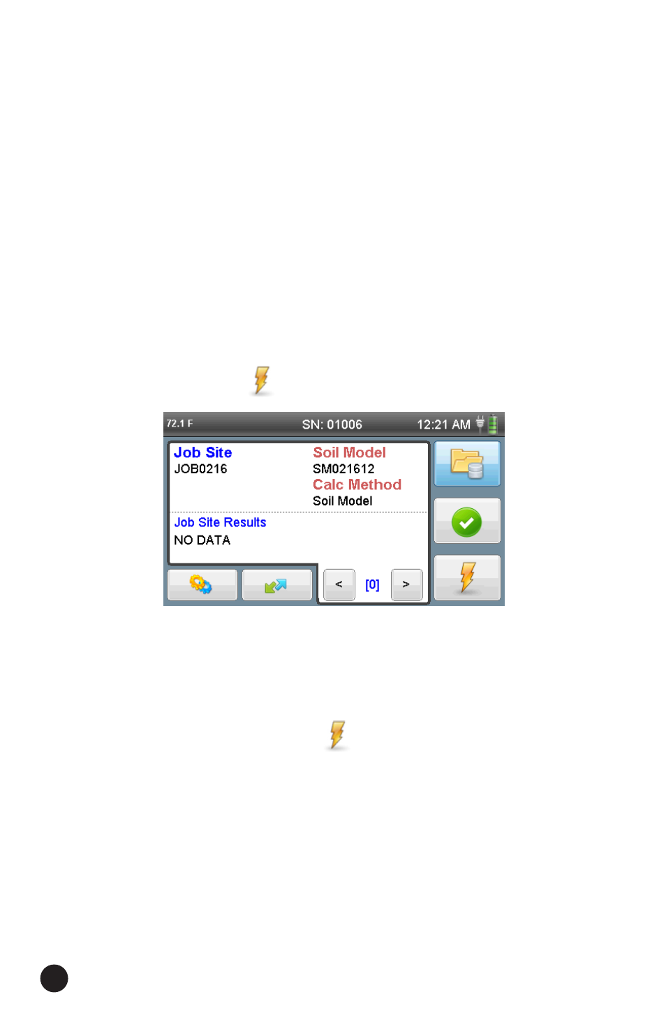
26. If you are already at the screen below from the previous step, simply
press the Test button
at the bottom right of the screen to begin
a test.
NOTE: If you have turned the gauge off and transported it to a test site,
when you turn the gauge back on, it will default to the last chosen
Project/Soil Model you were previously working with, which will return
you to the screen above.
When you press the Test button
, the screen below will appear.
As the directions on this screen state:
Verify that the Soil Sensor is connected to the darts.
Make sure the wires connected to the darts are not crossed.
Make sure the Temperature Sensor is connected and inserted into
the soil.
The diagram on the screen illustrates which darts should be connected
for a test. Tests always involve connection to opposing dart positions, or
in the first instance A and A. The diagram on the screen below illustrates
the correct position of the darts to use.
31