Baseline Systems Ethernet Radio User Manual
Page 14
Ethernet Radio Configuration Guide
Page 8
Section 2 – Adding a Repeater
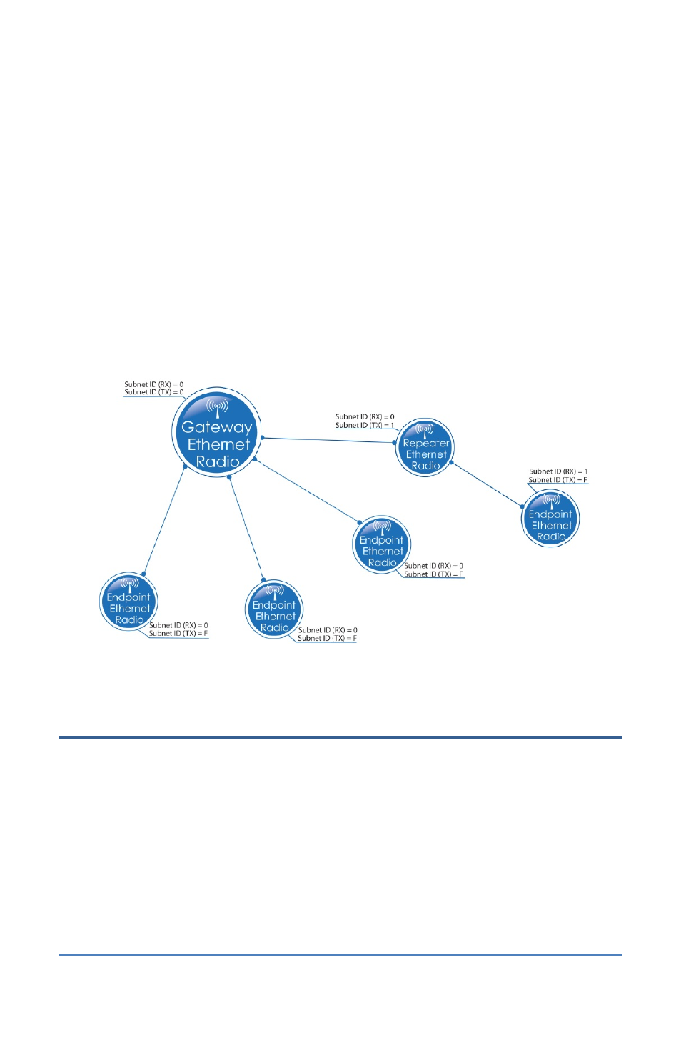
The example below shows a radio network where a Repeater has been added to one branch. Note
the following:
•
The values for the RX and TX Subnet IDs on the Gateway radio have been changed from the
default of F to 0.
•
On all Endpoint radios that receive and transmit directly to the Gateway have their RX Subnet
IDs set to 0, which tells them to “listen” to the Gateway, and their TX Subnet IDs are set to F,
which indicates that the device is the final in the line.
•
On the Repeater radio, the RX Subnet ID is set to 0, which tells it to “listen” to the Gateway.
The TX Subnet ID is set to 1, which serves to identify the Repeater.
•
On the Endpoint radio that is called through the Repeater, the RX Subnet ID is set to 1, which
tells that Endpoint to “listen” to the Repeater. The TX Subnet ID is set to F, which indicates
that the device is final in the line.
Step 2 – Install the Repeater Ethernet Radio at the Site
There are two options for adding a Repeater to an existing Ethernet radio network:
•
Install a Gateway Ethernet radio unit in its own enclosure, and then reconfigure it as a
Repeater. In this case, install the enclosure according to the instructions that came with the
unit, and then continue to Step 3 in this section.
•
Reconfigure one of your Endpoint Ethernet radio units as a Repeater. In this case, continue to
Step 3.