Marker adjustments, 12 marker adjustments – Great Plains NTA2000D Operator Manual User Manual
Page 35
33
9/13/2006
NTA 2000D 148-632M
Great Plains Mfg., Inc.
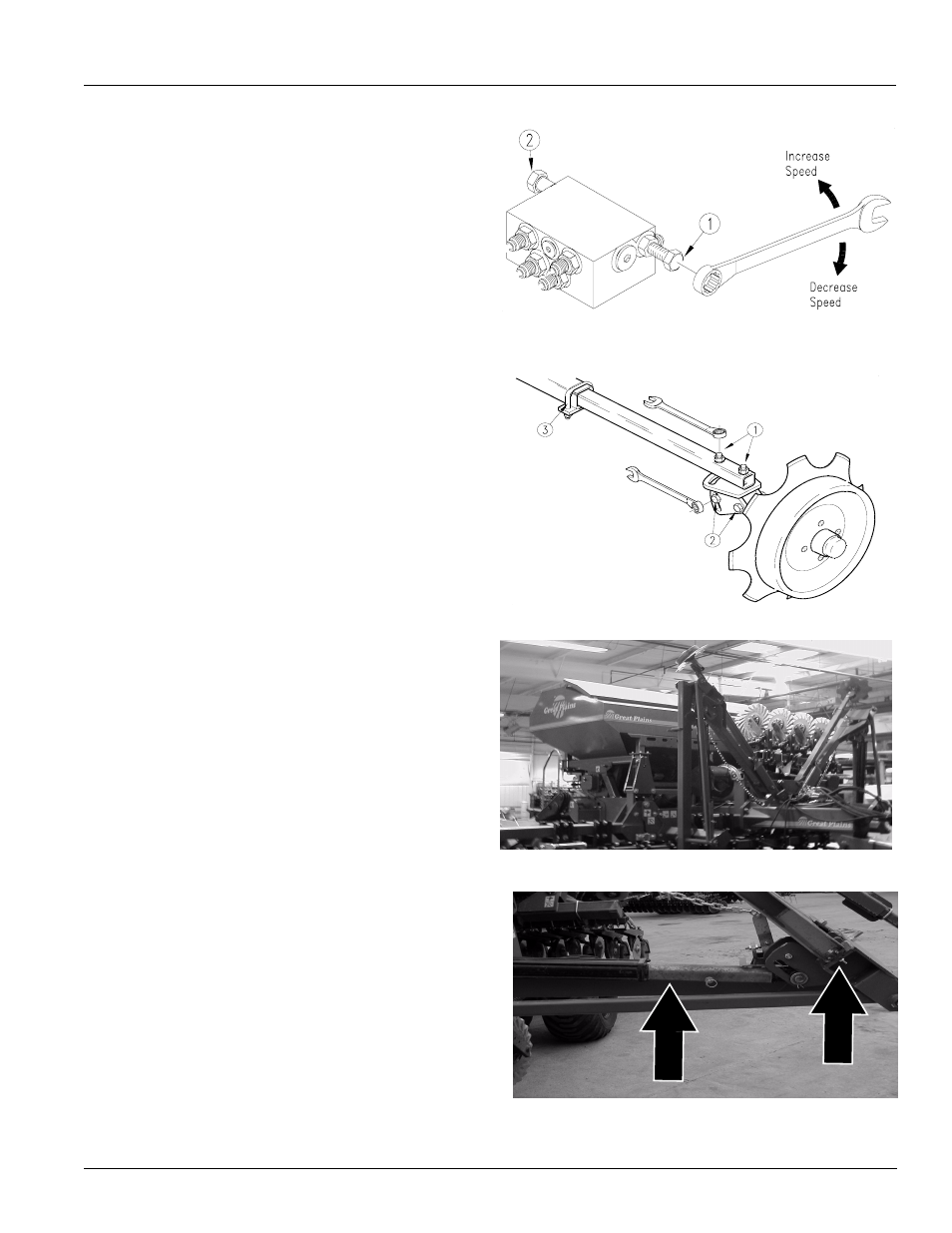
Figure 39
Speed Adjustment, Sequence Valve
Figure 40
Disk Angle
Figure 41
Marker Transport Position
Figure 42
Marker Field Position and Marker Breakaway Bolts
1
2
Marker Adjustments
Folding Speed
Refer to Figure 39
1.
Adjust folding speed with hex adjustment screws on
the sequence-valve body. There is one adjustment
screw for raising speed (1) and one for lowering speed
(2). Identify adjustment screws by markings stamped
in valve body.
2.
With tractor idling at a normal operating speed, adjust
marker folding to a safe speed.Turn adjustment
screws clockwise to decrease folding speed and
counterclockwise to increase folding speed. Exces-
sive folding speed could damage markers and void
the warranty.
3.
After adjusting the folding speed, tighten jam nuts on
hex adjustment screws to hold settings.
Disk Adjustments
Refer to Figure 40
If mark left by marker disk is not easy to see, change disk
angle to make a wider mark.
1.
Loosen two 1/2” carriage bolts (1) holding disk mount.
Rotate disk mount as desired.
If the marker disk is not square with the ground when the
marker is lowered in the field, or if marker arm tends to fold
up while lowered in the field, change disk angle relative to
ground.
2.
Loosen 1/2” bolts (2) and rotate marker mount until
marker disk is square with ground.
3.
To adjust where the disk marks, loosen U-bolt (3) and
slide marker-mount tube in or out as necessary. Re-
tighten U-bolt.
Cylinder Lock Channel
Refer to Figure 41
The markers should be in transport position when opening
a field or when drilling next to obstructions.
Refer to Figure 42
1.
For field operation the cylinder lock channels must be
placed on the cylinder rods so only the outer two sec-
tions of the markers fold. This speeds up marker cycle
time and reduces wear on markers.
2.
The markers have breakaway protection to keep them
from being damaged if the marker strikes a solid ob-
ject. The breakaway bolt should only be replaced with
a 3/8-16 x 2” Gr 5 bolt (Great Plains P/N 802-143C)
and two 3/8” nuts (Great Plains P/N 803-014C). It is
important to use two nuts on the breakaway bolt. Extra
bolts and nuts can be purchased and stored in the ex-
tra holes of the breakaway plate.
14048