Opener-subframe adjustment – Great Plains 2S-2600HDF Operator Manual v2 User Manual
Page 68
64
2S-2600HD
Great Plains Manufacturing, Inc.
195-069M
2014-02-03
Opener-Subframe Adjustment
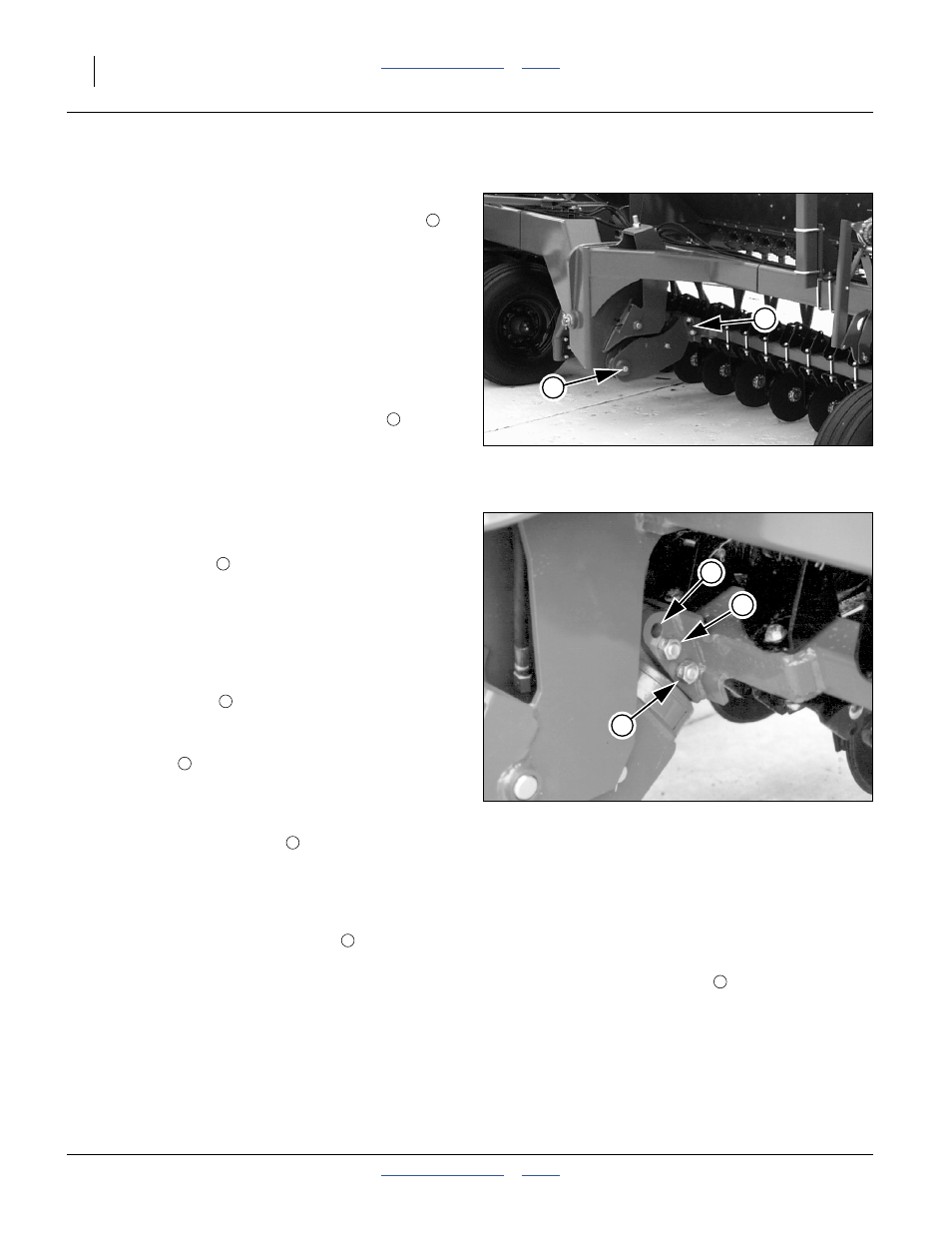
Refer to Figure 60
Each drill section has an opener frame which pivots
about the centerline of the drill gauge wheels. These
floating opener frames have the ability to rock the open-
ers 15 degrees up and 15 degrees down as a group. By
pivoting at the gauge wheels, openers maintain a consis-
tent depth as opener frames rock up and back.
Down pressure for each opener frame is provided by two
cylinders working on a constant lever arm. When com-
bined with live hydraulics, the cylinders provide constant
down pressure across the width of each opener frame –
regardless of how the frame is positioned. Two cylinders
per opener frame along with special trunnions
also
provide some ability for one end of an opener frame to
rock independent of the other while maintaining constant
opener down pressure across the frame.
At higher down-pressures (above 2100 psi), the row units
can tend to tip forward. An adjustment to the main-
frame/subframe pivot corrects this.The opener frame has
one adjustment point
for two different operating posi-
tions.
Refer to Figure 61 (shown in factory default configuration)
You can adjust opener frames between two operating
positions–one for normal down pressure and one for
higher down pressure. The adjustment is near the
opener frame pivots. There are three holes and two
bolts. The bottom bolt
serves as the pivot. The top bolt
is for adjustment.
• For normal drilling conditions, keep top bolt in second
(middle) hole
at all six frame pivots. Use this setting
when drilling with opener down pressure below 2100
psi.
• When drilling with opener down pressure above 2100
psi, place top bolt in top hole
on all six pivot points
across drill.
To change the bolts (to high pressure):
1.
Have a jack at hand.
2.
Loosen the nuts on all the top bolts
.
3.
Lower the opener sub-frames.
4.
Put the tractor hydraulic circuit for the openers in
float.
5.
Place jack under an opener tool bar at an arm.
6.
Lift the tool bar until the bolt is free.
7.
Remove the bolt.
8.
Repeat step 5 through step 7 the other arm of the
subframe.
9.
Raise the jack until the top holes are aligned.
10. Insert the bolt in the top hole
and spin on a nut.
11. Repeat step 5 through step 10 for each sub-frame.
12. Tighten all nuts.
Changing from high to low is similar, except lower the
jack at step 6 and reverse the bolt movement.
Figure 60
Opener-Frame Pivot
18857
1
2
1
2
Figure 61
Opener-Frame Adjustment
15558
3
4
5
2
3
4
5
4
5