Mortise installation instructions (continued), Step #2 – install outside & inside trim, Profile series exit device – SARGENT Profile Series Exit Devices User Manual
Page 11
9
800-810-WIRE (9473) • www.sargentlock.com • A7455B
Profile Series Exit Device
Copyright © 2003, 2008, Sargent Manufacturing Company
, an A
SSA ABL
O
Y
Group company
. All rights reserved.
Reproduction in whole or in part without the express written permission of Sargent Manufacturing Company is prohibited.
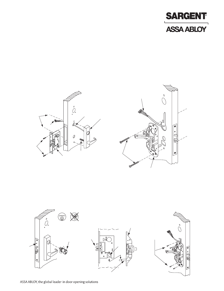
Mortise Installation Instructions (Continued)
Step #2 – Install Outside & Inside Trim
Outside of door
Inside of door
(2) Flat
head
wood
screws
ET Spindle
ET Control
Wire
harness
Mortise lock
Connector
Exit Chassis
Centerline for
(2) 1/4 - 20 x 2-3/8’’
flat head
machine
screws
(2) 1/4 - 20 x 2 3/8’’
Flat head
machine screws
Wire
harness
Outside of
door
Inside of
door
Cylinder
set
screw
Cylinder
Correct
Incorrect
Chassis
Lever
Latchbolt
Lever arm
(4) #10 Wood
screws
or #10-24
machine
screws
Figure 1
1. Exit Chassis:
• Route “ET” harness along track cutout for wood
doors and access hole for metal doors.
• Mount exit chassis carefully. Do not pinch
harness wires
• Position exit chassis on door so that lever arm is
under rear section of mortise lock lever. Then lift
up until latchbolt is completely retracted.
• Fasten exit chassis to door using (4) #10 wood
screws or #10-24 machine screws
2. Outside Trim
• Route harness through wire cutout and out to
other side of door
• Place “ET” control onto door
• Insert (2) 1/4-20 x 2-3/8 Flat head screws
• “ET” spindle will engage into mortise lock
3. Cylinder Installation
• Insert cylinder into “ET” control. Back out the
cylinder set screw in mortise lock
• Thread cylinder clockwise into mortise lock
until the cylinder sits flush and correct in
“ET” control (see figure 1)
• Tighten cylinder set screw