Mortise installation instructions (continued), Passport 1000 pg exit device, 6a – installation of inside component assembly – SARGENT Passport 1000 PG Exit Devices User Manual
Page 19: 6b - installation of connectors
Mortise Installation Instructions (Continued)
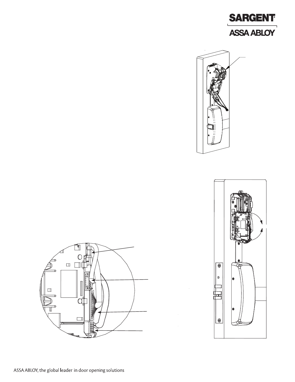
6A – Installation of Inside Component Assembly
1. Insert bottom of component assembly first (Fig. 6A).
2. Clip top of component assembly to mounting plate verifying
both tabs attached securely.
6B - Installation of Connectors
Modular
component
Fig. 6A
Inside of door
From ET Control
From Outside Trim (LCU
Card Reader)
From Outside Trim
(Keypad)
From Outside Trim
(ground)
Fig. 6B2
Detail
Fig. 6B1
Detail
Secure the following connectors onto the circuit board (Fig. 6B1 and 6B2):
1. Secure the mortise lock body assembly connector (10-pin).
2. Secure the mortise keypad/card reader connector (14-pin).
3. Secure the LCU connector (7-pin).
NOTES:
• Connectors go on only one way.
• Do not force and do not offset connectors.
• Be sure they are completely seated (flush).
10/31/12
A7809B 19
Copyright © 2012, Sargent Manufacturing Company
, an ASSA ABLOY Group company
. All rights reser
ved.
Reproductions in whole or in part without express written permission of Sargent Manufacturing Company is prohibited.
Passport 1000 PG Exit Device