Rim installation instructions (continued), Passport 1000 pg exit device – SARGENT Passport 1000 PG Exit Devices User Manual
Page 11
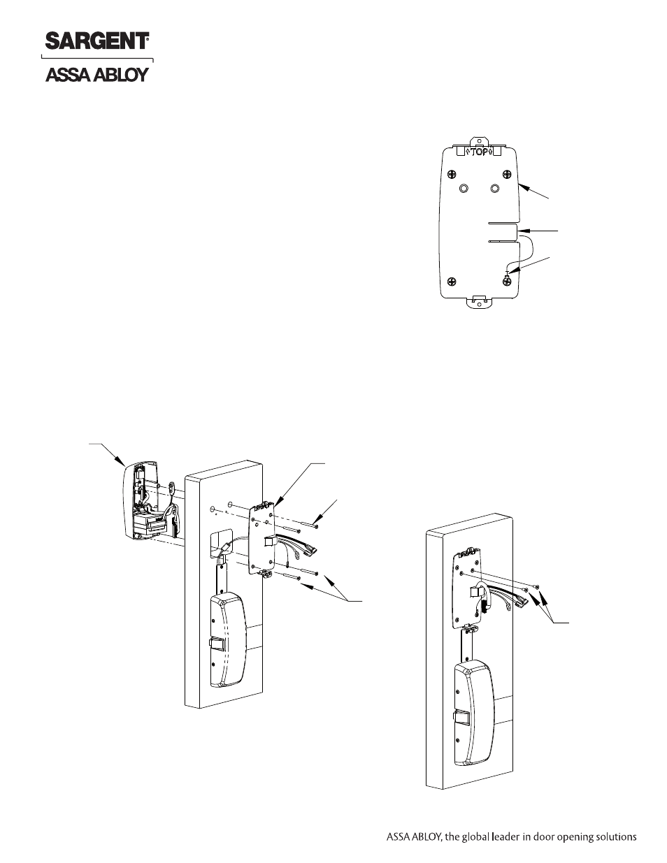
Outside
Passport
Trim
Inside of door
Fig. 5B1
Mounting
plate
(4) #8-32 x 1-7/8” flat head
machine screws
Attach ground
lug to bottom
right screw
Fig. 5C
Mounting plate
Cables
Position lug upright,
then tighten
screw
1. Insert the mounting posts through holes as shown (Fig. 5B1).
2. On the inside of the door, position the mounting plate over the indicated
holes. As you feed controller, keypad, battery and grounding cables thru
side opening (Fig. 5B1), tuck the ferrite bead safely under the reader.
Note: Inserting either of the top corner screws at this point will hold
the plate as you feed the cables through. (Also refer to Step 6B)
3. Attach grounding lug to bottom right screw and note upright
positioning of lug as shown (Fig. 5B2).
4. Insert other corner screws and tighten all, fastening the outside
escutcheon to the door (Fig. 5B1).
IMPORTANT If the following step is skipped, the product
will not be UL-compliant:
5. Attach two (2) #8 x 3/8” flat head wood screws for wood doors, or
(2) #8-32 x 3/8” flat head machine screws for metal doors (Fig. 5C).
Tighten securely.
Fig. 5B2
(2) #8 - 3/8” flat head
wood screws or
(2) #8 -3/8”
flat head
machine screws
Rim Installation Instructions (Continued)
Inside of door
5B – Installation of Outside Escutcheon & Mounting
Plate Assembly
11
A7809B
Copyright © 2012, Sargent Manufacturing Company
, an ASSA ABLOY Group company
. All rights reser
ved.
Reproductions in whole or in part without express written permission of Sargent Manufacturing Company is prohibited.
10/31/12
Passport 1000 PG Exit Device