Aluminium 300a bevel cut n, Plasma / h, O shield – Tweco XT-300 Torch for OEM UC-300 User Manual
Page 75
Manual 0-4829 Rev AN
8-77
TORCH DATA for Ultra-Cut
Shield
22-1046
in
in
psi
Ball
psi
Ball
psi
(ipm)
(in)
(sec)
(in)
1/2
0.08
20
120 100
8
55
120
0.300
0.3
0.161
5/8
0.08
20
120 100
8
55
100
0.300
0.4
0.165
3/4
0.08
20
120 100
8
55
80
0.500
0.5
0.174
7/8
0.08
20
120 100
8
55
70
0.500
0.6
0.175
1
0.08
20
120 100
8
55
60
0.500
0.7
0.190
1 1/4 0.08
20
120 100
8
55
40
0.500
1.2
0.185
1 1/2
0.08
20
120 100
8
55
25
0.190
1 3/4 0.08
20
120 100
8
55
15
0.213
2
0.08
20
120 100
8
55
10
0.205
mm
mm
bar
Ball
bar
Ball
bar
(mm/min)
(mm)
(sec)
(mm)
15
2.00
1.4
120
6.9
8
3.8
2680
7.6
0.4
4.2
20
2.00
1.4
120
6.9
8
3.8
1960
12.7
0.5
4.4
25
2.00
1.4
120
6.9
8
3.8
1560
12.2
0.7
4.8
32
2.00
1.4
120
6.9
8
3.8
1000
0.2
1.2
4.7
38
2.00
1.4
120
6.9
8
3.8
640
4.8
44
2.00
1.4
120
6.9
8
3.8
400
5.4
50
2.00
1.4
120
6.9
8
3.8
270
5.2
(mm)
5.1-11.4
6.4-11.4
7.6-11.4
6.4-11.4
6.4-11.4
7.6-11.4
7.6-11.4
* Pressure of the water supply line should be regulated by customer pressure regulator.
Note1: Ohmic height sensing is not recommended with water shield. Water on the plate interferes electrically
with the ohmic sensing circuit.
Note2: Water source used for shield must be demineralized.
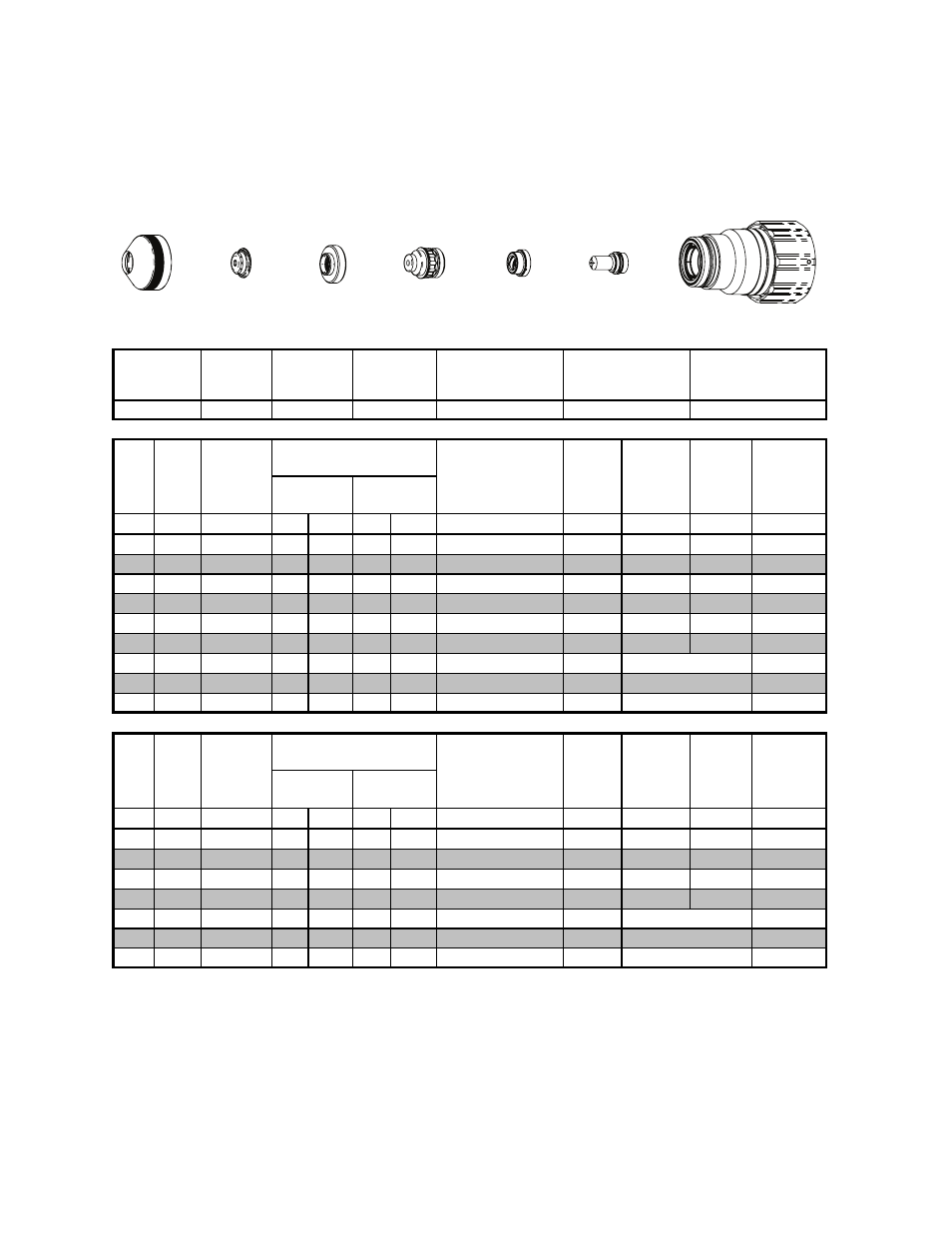
Plasma Gas
Distributor
Electrode
Cartridge
Shield
Retainer
Shield Gas
Distributor
Tip
22-1043
22-1089
22-1022
22-1015
22-1284
22-1066
Kerf Width
@ Rec.
Speed
Plasma
(N
2
)
Shield
(H
2
O)*
Pre Flow
Pressure
(N
2
)
Cut Flow Rates /
Pressures
Effective Cut
Height
Travel
Speed
Initial
Piercing
Height
Pierce
Delay
Ef
fe
ct
iv
e
Ma
te
ri
a
l
M
in
imu
m
C
lear
a
n
ce
(in)
.200-.450
.200-.450
.250-.450
.250-.450
Edge Start
Edge Start
.250-.450
.250-.450
.300-.450
.300-.450
Edge Start
Pre Flow
Pressure
(N
2
)
Cut Flow Rates /
Pressures
Travel
Speed
Initial
Piercing
Height
Pierce
Delay
.300-.450
Effective Cut
Height
Aluminium
300A Bevel Cut
N
2
Plasma / H
2
O Shield
BOLD TYPE indicates maximum piercing parameters. BOLD ITALIC indicates edge starts only.
Edge Start
Edge Start
Edge Start
Kerf Width
@ Rec.
Speed
Plasma
(N
2
)
Shield
(H
2
O)*
Mi
n
imu
m
C
lear
anc
e
Ef
fe
ct
iv
e
Ma
te
ri
a
l
Cartridge
Electrode
Shield
Shield Gas
Distributor
Tip
Plasma Gas
Distributor
Shield Retainer
Art # A-08552
This Art Is For Reference ONLY