Stainless steel 100a n, Plasma / h, O shield – Tweco XT-300 Torch for OEM UC-300 User Manual
Page 25
Manual 0-4829 Rev AN
8-27
TORCH DATA for Ultra-Cut
(ga)
(in)
inch
(PSI)
(Ball) (PSI) (Ball) (PSI)
Volts
(in)
±0.005
(ipm)
(in)
(sec)
(in)
3/16
0.188
45
60
90
7
55
148
0.100
140
0.300
0.1
0.091
1/4
0.250
45
60
90
7
55
158
0.100
95
0.300
0.1
0.091
3/8
0.375
45
60
90
7
55
168
0.150
65
0.350
0.2
0.100
1/2
0.500
45
60
90
7
55
168
0.150
50
0.350
0.4
0.102
(Bar)
(Ball) (Bar) (Ball) (Bar)
Volts
(mm)
±0.1
(mm/min)
(mm)
(sec)
(mm)
3.1
60
6.2
7
3.8
149
2.5
3390
7.6
0.1
2.3
3.1
60
6.2
7
3.8
156
2.5
2665
7.6
0.1
2.3
3.1
60
6.2
7
3.8
163
3.8
2015
8.9
0.2
2.5
3.1
60
6.2
7
3.8
168
3.8
1595
8.9
0.3
2.6
3.1
60
6.2
7
3.8
168
3.8
1355
8.9
0.4
2.6
(PSI) /
(Bar)
(Ball)
(PSI) /
(Bar)
(Ball)
(PSI) /
(Bar)
Volts
in ±0.005 /
mm ±0.1
ipm /
mm/min
in ±0.005 /
mm ±0.1
(sec)
20
40
80
0.120
300
0.120
1.4
2.8
5.5
3.0
7600
3.0
150
0
BOLD TYPE indicates maximum piercing parameters.
Burn-through
may occur
for thicknesses
< 1/16" (0.063") / 1.6
mm.
Plasma (N
2
) Shield
(N
2
)
50
75
Travel
Speed
Initial
Transfer
Height
Pierce
Delay
Marking
quality
degrades
as
thickness
decreases
Travel
Speed
Initial
Piercing
Height
Pierce
Delay
Kerf Width
@ Rec.
Speed
Pre Flow
Pressure
(Air)
Cut Flow Rates /
Pressures
Arc
Voltage
Torch
Working
Height
Plasma (N
2
)
Shield
(H
2
O)*
Travel
Speed
Initial
Piercing
Height
Pierce
Delay
Kerf Width
@ Rec.
Speed
Pre Flow
Pressure
(Air)
Cut Flow Rates /
Pressures
Arc
Voltage
Torch
Working
Height
Plasma (N
2
)
Shield
(H
2
O)*
12
8
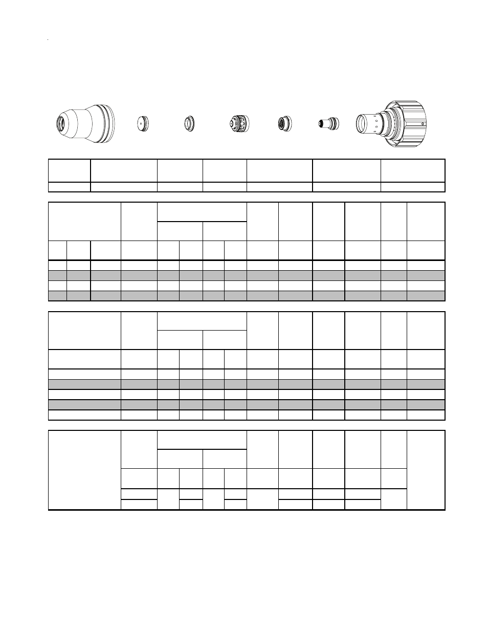
Stainless Steel
100A
N
2
Plasma / H
2
O Shield
Shield Cup
Shield Cap
Shield Gas
Distributor
Tip
Plasma Gas
Distributor
Electrode
Cartridge
Material
Thickness
Torch
Working
Height
(mm)
5
6
18A Arc Current
Pre Flow
Pressure
(N
2
)
Cut Flow Rates /
Pressures
Arc
Voltage
10
Material
Thickness
22-1016
Marking
22-1036
22-1274
22-1053
22-1041
22-1089
22-1020
Electrode
Shield Cap
Tip
Shield Gas
Distributor
Plasma Gas
Distributor
Cartridge
Shield Cup
This Art Is For Reference ONLY
Art # A-07958_AB