Aluminium 30a air plasma / air shield – Tweco XT-300 Torch for OEM UC-300 User Manual
Page 10
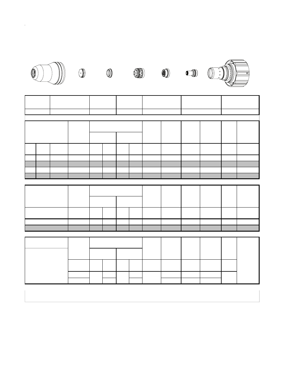
TORCH DATA for Ultra-Cut
8-12
Manual 0-4829 Rev AN
(ga)
(in)
inch
(PSI)
(Ball) (PSI) (Ball) (PSI)
Volts
(in)
±0.005
(ipm)
(in)
(sec)
(in)
25
0.025
60
60
120
15
120
86
0.020
500
0.040
0.0
0.029
21
0.037
60
60
120
15
120
86
0.020
240
0.060
0.1
0.046
18
0.052
60
60
120
15
120
84
0.020
230
0.100
0.2
0.034
16
0.064
60
60
120
15
120
80
0.020
220
0.100
0.2
0.036
(Bar)
(Ball) (Bar) (Ball) (Bar)
Volts
(mm)
±0.1
(mm/min)
(mm)
(sec)
(mm)
4.1
60
8.3
15
8.3
86
0.5
6060
1.7
0.1
0.9
4.1
60
8.3
15
8.3
75
0.5
5280
2.5
0.2
0.9
(PSI) /
(Bar)
(Ball)
(PSI) /
(Bar)
(Ball)
(PSI) /
(Bar)
Volts
in ±0.005 /
mm ±0.1
ipm /
mm/min
in ±0.005 /
mm ±0.1
(sec)
20
40
80
0.100
300
0.100
1.4
2.8
5.5
2.5
7600
2.5
BOLD TYPE indicates maximum piercing parameters. BOLD ITALIC indicates edge starts only.
Marking
quality
degrades
as
thickness
decreases
Burn-through
may occur
for thicknesses
< 1/16" (0.063") / 1.6
mm.
Plasma (N
2
) Shield
(N
2
)
20
70
93
0
Torch
Working
Height
Travel
Speed
Initial
Transfer
Height
Pierce
Delay
16A Arc Current
Pre Flow
Pressure
(N
2
)
Cut Flow Rates /
Pressures
Arc
Voltage
(mm)
1
2
Marking
Pierce
Delay
Kerf Width
@ Rec.
Speed
Plasma (O
2
) Shield
(Air)
Kerf Width
@ Rec.
Speed
Plasma (Air) Shield (Air)
Material
Thickness
Pre Flow
Pressure
(Air)
Cut Flow Rates /
Pressures
Arc
Voltage
Torch
Working
Height
Travel
Speed
Initial
Piercing
Height
Torch
Working
Height
Travel
Speed
Initial
Piercing
Height
Pierce
Delay
Material
Thickness
Pre Flow
Pressure
(Air)
Cut Flow Rates /
Pressures
Arc
Voltage
22-1045
22-1077
22-1020
22-1016
22-1033
22-1274
22-1059
Aluminium
30A
Air Plasma / Air Shield
Shield Cup
Shield Cap
Shield Gas
Distributor
Tip
Plasma Gas
Distributor
Electrode
Cartridge
Electrode
Shield Cap
Tip
Shield Gas
Distributor
Plasma Gas
Distributor
Cartridge
Shield Cup
This Art Is For Reference ONLY
Art # A-07958_AB