Aluminium 300a n, Plasma / h, O shield – Tweco XT-300 Torch for OEM UC-300 User Manual
Page 68
TORCH DATA for Ultra-Cut
8-70
Manual 0-4829 Rev AN
(ga)
(in)
inch
psi
Ball
psi
Ball
psi
Volts
(in)
±0.005
(ipm)
(in)
(sec)
(in)
1/2
0.500
20
120
100
8
55
160
0.200
120
0.300
0.3
0.161
5/8
0.625
20
120
100
8
55
164
0.200
100
0.300
0.4
0.165
3/4
0.750
20
120
100
8
55
170
0.250
80
0.500
0.5
0.174
7/8
0.875
20
120
100
8
55
173
0.250
70
0.500
0.6
0.175
1
1.000
20
120
100
8
55
175
0.250
60
0.500
0.7
0.190
1 1/4
1.250
20
120
100
8
55
180
0.250
40
0.500
1.2
0.185
1 1/2
1.500
20
120
100
8
55
184
0.300
25
0.190
1 3/4
1.750
20
120
100
8
55
196
0.300
15
0.213
2
2.000
20
120
100
8
55
200
0.300
10
0.205
bar
Ball
bar
Ball
bar
Volts
(mm)
±0.1
(mm/min)
(mm)
(sec)
(mm)
1.4
120
6.9
8
3.8
163
5.1
2680
7.6
0.4
4.2
1.4
120
6.9
8
3.8
171
6.4
1960
12.7
0.5
4.4
1.4
120
6.9
8
3.8
175
6.4
1560
12.2
0.7
4.8
1.4
120
6.9
8
3.8
180
6.4
1000
0.2
1.2
4.7
1.4
120
6.9
8
3.8
184
7.6
640
4.8
1.4
120
6.9
8
3.8
195
7.6
400
5.4
1.4
120
6.9
8
3.8
199
7.6
270
5.2
(PSI) /
(Bar)
(Ball)
(PSI) /
(Bar)
(Ball)
(PSI) /
(Bar)
Volts
in ±0.005 /
mm ±0.1
ipm /
mm/min
in ±0.005 /
mm ±0.1
(sec)
15
60
90
0.120
300
0.120
1.0
4.1
6.2
3.0
7600
3.0
115
0
Plasma (N
2
) Shield (N
2
)
80
NA
Marking
24A Arc Current
Pre Flow
Pressure
(N
2
)
Cut Flow Rates /
Pressures
Arc
Voltage
Torch
Working
Height
Travel
Speed
Initial
Transfer
Height
Pierce
Delay
Marking
quality
degrades
as
thickness
decreases
* Pressure of the water supply line should be regulated by customer pressure regulator.
Note1: Ohmic height sensing is not recommended with water shield. Water on the plate interferes electrically with the
ohmic sensing circuit.
Note2: Water source used for shield must be demineralized.
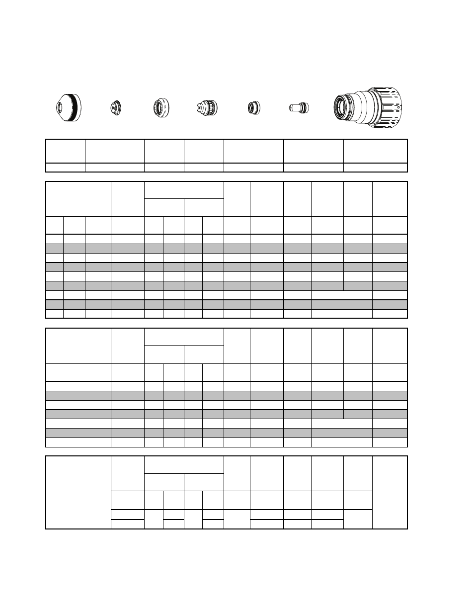
Plasma Gas
Distributor
Electrode
Cartridge
Shield
Retainer
Shield Cap
Shield Gas
Distributor
Tip
22-1043
22-1089
22-1022
22-1015
22-1046
22-1284
22-1066
Material
Thickness
Pre Flow
Pressure
(N
2
)
Cut Flow Rates /
Pressures
Arc
Voltage
Kerf Width
@ Rec.
Speed
Plasma (N
2
)
Shield
(H
2
O)*
Edge Start
Torch
Working
Height
Travel
Speed
Initial
Piercing
Height
Pierce
Delay
Edge Start
Edge Start
Material
Thickness
Pre Flow
Pressure
(N
2
)
Cut Flow Rates /
Pressures
Arc
Voltage
Torch
Working
Height
Travel
Speed
Initial
Piercing
Height
Pierce
Delay
25
32
Kerf Width
@ Rec.
Speed
Plasma (N
2
)
Shield
(H
2
O)*
(mm)
Aluminium
300A
N
2
Plasma / H
2
O Shield
BOLD TYPE indicates maximum piercing parameters. BOLD ITALIC indicates edge starts only.
50
Edge Start
38
Edge Start
44
Edge Start
15
20
Cartridge
Electrode
Shield
Shield Gas
Distributor
Tip
Plasma Gas
Distributor
Shield Retainer
Art # A-07917_AC
This Art Is For Reference ONLY