Shield – Tweco XT-300 Torch for OEM UC-300 User Manual
Page 67
Manual 0-4829 Rev AN
8-69
TORCH DATA for Ultra-Cut
(ga)
(in)
inch
psi
Ball
psi
Ball
psi
Volts
(in)
±0.005
(ipm)
(in)
(sec)
(in)
1/4
0.250
20
120
100
NA
120
163
0.400
300
0.400
0.1
0.182
3/8
0.375
20
120
100
NA
120
163
0.400
275
0.400
0.2
0.186
1/2
0.500
20
120
100
NA
120
153
0.300
210
0.400
0.3
0.174
5/8
0.625
20
120
100
NA
90
160
0.300
140
0.350
0.4
0.169
3/4
0.750
20
120
100
NA
90
159
0.300
110
0.350
0.5
0.172
7/8
0.875
20
120
100
NA
90
162
0.300
95
0.400
0.6
0.183
1 1.000
20
120
100
NA
120
165
0.350
85
0.450
0.7
0.190
1 1/4
1.250
20
120
100
NA
120
168
0.400
60
0.205
1 1/2
1.500
20
120
100
NA
120
177
0.400
45
0.215
1 3/4
1.750
20
120
100
NA
120
182
0.400
35
0.226
2
2.000
20
120
100
NA
120
188
0.400
25
0.215
bar
Ball
bar
Ball
bar
Volts
(mm)
±0.1
(mm/min)
(mm)
(sec)
(mm)
1.4
120
6.9
NA
8.3
163
10.2
7620
10.2
0.1
4.7
1.4
120
6.9
NA
8.3
163
10.2
7290
10.2
0.2
4.7
1.4
120
6.9
NA
8.3
162
9.8
6740
10.2
0.2
4.7
1.4
120
6.9
NA
8.3
155
8.2
5700
10.2
0.3
4.5
1.4
120
6.9
NA
6.2
158
7.6
4050
9.2
0.4
4.3
1.4
120
6.9
NA
6.2
160
7.6
2680
9.3
0.5
4.5
1.4
120
6.9
NA
8.3
165
8.7
2190
11.3
0.7
4.8
1.4
120
6.9
NA
8.3
168
10.2
1510
5.2
1.4
120
6.9
NA
8.3
177
10.2
1150
5.5
1.4
120
6.9
NA
8.3
182
10.2
910
5.7
1.4
120
6.9
NA
8.3
185
10.2
670
5.8
(PSI) /
(Bar)
(Ball)
(PSI) /
(Bar)
(Ball)
(PSI) /
(Bar)
Volts
in ±0.005 /
mm ±0.1
ipm /
mm/min
in ±0.005 /
mm ±0.1
(sec)
15
60
90
0.120
300
0.120
1.0
4.1
6.2
3.0
7600
3.0
Initial
Transfer
Height
Pierce
Delay
Marking
quality
degrades
as
thickness
decreases
Burn-through
may occur
for thicknesses
< 1/16" (0.063") / 1.6
mm.
Plasma (N
2
) Shield (N
2
)
80
NA
135
0
Cut Flow Rates /
Pressures
Arc
Voltage
Torch
Working
Height
Travel
Speed
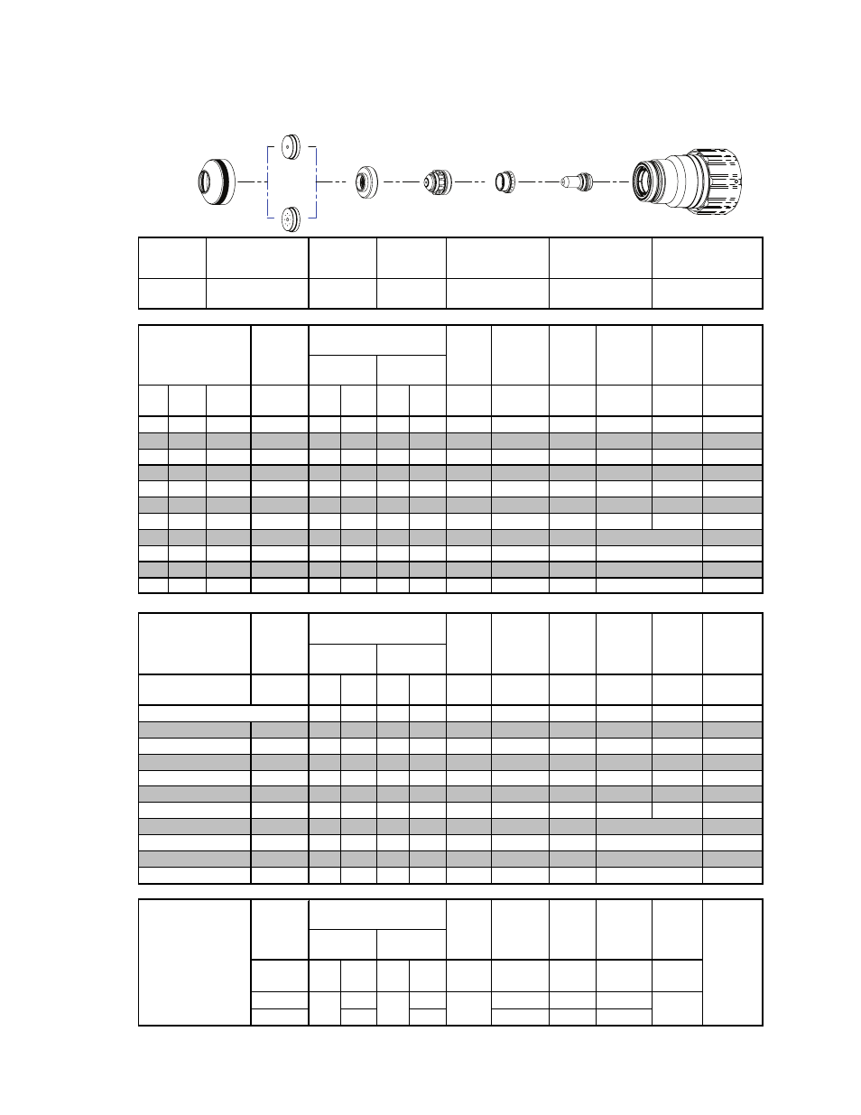
Plasma Gas
Distributor
Electrode
Cartridge
Shield
Retainer
Shield Cap
Shield Gas
Distributor
Tip
22-1041
22-1091
22-1022
22-1015
< 1" / 25mm 22-1038,
1" / 25mm + 22-1039
22-1284
22-1065
Material
Thickness
Pre Flow
Pressure
(N
2
)
Cut Flow Rates /
Pressures
Arc
Voltage
Edge Start
Edge Start
Kerf Width
@ Rec.
Speed
Plasma
(H35)
Shield (N
2
)
Torch
Working
Height
Travel
Speed
Initial
Piercing
Height
Pierce
Delay
Aluminium
300A
H35 Plasma / N
2
Shield
15
10
12
(mm)
6
8
Kerf Width
@ Rec.
Speed
Plasma
(H35)
Shield (N
2
)
Edge Start
Edge Start
Material
Thickness
Pre Flow
Pressure
(N
2
)
Cut Flow Rates /
Pressures
Arc
Voltage
Torch
Working
Height
Travel
Speed
Initial
Piercing
Height
Pierce
Delay
20
25
32
Edge Start
50
Edge Start
BOLD TYPE indicates maximum piercing parameters. BOLD ITALIC indicates edge starts only.
38
Edge Start
44
Edge Start
Marking
24A Arc Current
Pre Flow
Pressure
(N
2
)
Electrode
Shield Retainer
Tip
Art # A-08567
Plasma Gas
Distributor
Cartridge Assembly
This Art Is For Reference ONLY
Shield Cap
Shield Gas
Distributor