Nozzle cleaning station, 01 maintenance schedule, 02 component replacement instructions – Tweco QRC-2000 User Manual
Page 17
nozzle cleaning station
5-15
SM-QRC-2000
MAintenAnCe
SECTION 5:
MAINTENANCE
5.01 Maintenance Schedule
The QRC
TM
-2000 will require a periodic maintenance
schedule to ensure an optimum service life. The following
maintenance checks are required. Depending on the use
of the unit, each specific application could require a more
extensive schedule.
Daily
Ensure incline housing area is clear of excessive
spatter.
Visually check oil level in lubricator reservoir.
Weekly
Ensure incline housing area is clear of excessive
spatter.
Visually check lubricating oil level in lubricator
reservoir. The life of the air motor is dependent on
a sufficient supply of lubricating oil. Replenish this
oil as needed.
Inspect air lines and connections for leaks.
Check interface cables for frayed connections or
bad wiring.
Quarterly
The QRC
TM
-2000 reamer blade life will depend on the
application.
At least quarterly the reamer blade should be inspected
for dullness, clogging and breakage.
Visually check lubricating oil level in lubricator reservoir.
Ensure incline housing area is clear of excessive spatter.
Yearly
The clamp block should be cleaned and inspected
for excessive wear and replaced if needed.
Visually check lubricating oil level in lubricator
reservoir. Replenish this oil as needed.
Inspect air lines and connections for leaks.
Check interface cables for frayed connections or
bad wiring.
Remove top plate and apply grease on cam slides
on top (V-Block) and side plates.
•
•
•
•
•
•
•
•
•
•
•
•
•
•
•
5.02 Component Replacement Instructions
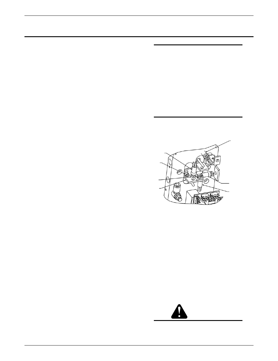
Upper, Lower, and Jaw Stop Limit Switches
Ensure that the power is off and disconnected, and the air
supply is off before replacing the limit switches.
To replace the limit switches, loosen the screws that
connect the limit switch bracket to the manifold.
Disconnect the wiring for the limit switch that is being
replaced.
Remove the nut that connects the limit switch to the limit
switch bracket.
Replace the limit switches in reverse order
•
•
•
•
NOTE
be sure to review the wiring diagram when
rewiring and disconnecting the limit switch (see
figure 12). the limit switches are adjusted at
the factory. if an adjustment needs to be made,
please contact our factory technical center.
Reset Switch
Unscrew the nut that connects the limit switch to
bracket.
Disconnect the wiring from the circuit board and
replace it.
NOTE
be sure to review the wiring diagram (figure
12) when rewiring and disconnecting the reset
switch.
•
•
Circuit Board
Ensure that the power and air supply are off and
disconnected before replacing the circuit board.
Replace the circuit board in the following manner:
Once the power and air are disconnected from the
QRC
TM
-2000, carefully unplug all connectors from
the board.
Unscrew the two screws located on the circuit board.
(Fig. 17) The circuit board can now be replaced.
Install the new circuit board on the board insulator.
Once this has been completed, tighten the two circuit
board mounting screws.
Reconnect the connectors while referring to wiring
diagram to be sure the connections are in the
proper location.
CAUTION
Do not switch circuit board sourcing and
sinking switches with the power on. damage
will occur. only move the switches with the
power off.
•
•
•
•
•
LOWER
LIMIT
SWITCH
BRACKET
SCREW
LOCKING
NUT
SWITCH
BRACKET
JAW CLAMP
LIMIT
SWITCH
RESET
SWITCH
UPPER LIMIT
SWITCH
Figure 16