Nozzle cleaning station, 02 wiring diagram, Figure 12 – Tweco QRC-2000 User Manual
Page 15: Figure 11: pin #1 on top/pin #6 on bottom
nozzle cleaning station
4-13
SM-QRC-2000
WiRing And pneuMAtiC
SECTION 4:
WIRING AND PNEUMATIC
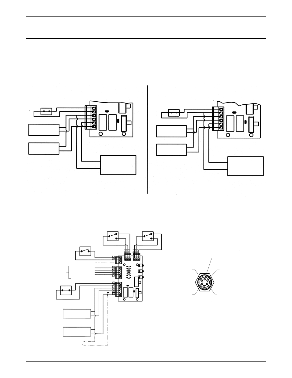
4.01 Wiring for the QRM-100 and QRM-3 Anti-spatter Mist Applicator
The drawings below show the QRM-100 and QRM-3 wiring connections.
For a sinking connection, the wires must be connected to positions 5 and 2. For sourcing connection, the wires
must be connected to positions 5 and 3.
To operate the QRM-100 Anti-Spatter Mist Applicator, a timed 24 V DC signal must be applied to the black lead
(spare) of the interface receptacle.
•
•
MOTOR & CLAMP
SOLENOID VALVE
SPINDLE LIFT
SOLENOID VALVE
PIN #5
PIN #3
ANTISPATTER UNIT
24DC
MOTOR & CLAMP
SOLENOID VALVE
SPINDLE LIFT
SOLENOID VALVE
PIN #5
PIN #2
ANTISPATTER UNIT
24DC
SOURCING
SINKING
4.02 Wiring Diagram
Figure 12
LOWER LIMIT
SWITCH
UPPER LIMIT
SWITCH
CLAMP
RETURN LIMIT
SWITCH
NOT USED
START SIGNAL
COMMON
+24VDC
JAWS UNCLAMPED
OPTIONAL EQUIPMENT
SEE 5 PIN
CONNECTOR
WIRING
RESET SWITCH
MOTOR AND CLAMP
SOLENOID VALVE
SPINDLE LIFT
SOLENOID VALVE
OPTIONAL
EQUIPMENT
PIN #4
(ORG) START
SIGNAL
PIN #5 (BLK)
OPTION
PIN #3
(GRN) JAWS
UNCLAMPED
PIN #2 (RED)
+24 VDC
PIN #1 (WHT)
COMMON
EXTERNAL VIEW OF 5-PIN CONNECTOR
Figure 11: Pin #1 on Top/Pin #6 on Bottom