Nozzle cleaning station, 04 qrc, 2000 wiring interface – Tweco QRC-2000 User Manual
Page 10
nozzle cleaning station
3-8
SM-QRC-2000
inStAllAtion And opeRAtion
3.03 Air Supply, Connections, and
Lubrication Requirements
The air supply for the QRC
TM
-2000 nozzle cleaning station
should be filtered, unlubricated air. This unit requires 80-
100 PSI @ 8 CFM (5.5 – 6.8 BAR @ 225 LPM). The air
supply line should be a minimum of 1/4” I.D. with a male
1/4” NPT connection to fit the female connection in the
side of the logic cover. The air motor is lubricated through
a servo meter located below the lubricator reservoir.
The servo meter injects a quantity of oil directly into
the solenoid valves and air motor during each cleaning
cycle. The lubrication should be done using a light grade
hydraulic oil with a viscosity rating of 150 VC 15-20 (SAE
5W). When filling the reservoir for the first time or refilling
an empty reservoir, you must manually prime the pump to
distribute the oil through the system. The servo meter has
an adjustment that goes from 0 (-) to 45 (+) clicks and a
push button to prime the lubricant oil. Refer to Figure 2.
Pull the servo meter knob to the unlock position (A).
Set the servo meter knob at 45 (+) and press the button
appromimately 50 to 60 times.
Turn the servo meter knob counter-clockwise to 0 (-)
and set at 3 (+) clicks.
Push the servo meter knob back into the locked position (C).
The amount of lubricant can be adjusted by turning the
adjustment knob located on the servo meter.
•
•
•
•
LUBRICATOR
RESERVOIR
SERVO
METER
Figure 2
SERVO
METER
KNOB
PRIMER
PUSH
BUTTON
NOTE
Do not run unit without lubricant oil. if unit runs
out of lubricant oil, the motor will lock up and
the solenoid valves will stick. When lubricant
oil is added you must prime the unit and check
operation of the solenoid valves. permanent
damage can be caused to the solenoid valves if
the unit is allowed to run out of lubricant oil.
NOTE
lubricator Reservoir oil must have a vent in the
open position. if not, oil will not flow.
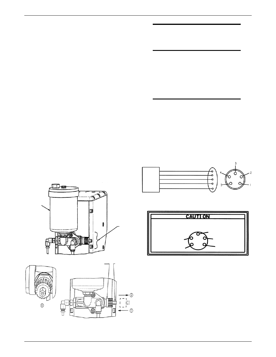
3.04 QRC
TM
-2000 Wiring Interface
The QRC
TM
-2000 Nozzle Cleaning Station wiring interface
requires a five wire connection. Each wire is color-coded.
The drawing below shows the wire color to its connector
pin/socket number and function.
The Following Connections are Required for Proper
Unit Operation:
Red Lead Connection: Operates internal logic with
a +24 V DC supply.
Green Lead Connection: Cycle complete output
signal (+24 V DC for sourcing logic signal; 0 V DC
for sinking logic signal).
White Lead Connection: Supply common.
Orange Lead Connection: Cycle start input signal
+24 V DC for sourcing logic signal; 0 V DC for sinking
logic signal. (.5 - 1.0 second pulse signal)
Black Lead: Spare wire (optional connection).
•
•
•
•
•
NOTE
the QRC2000 nozzle cleaning station is factory
preset at 3 (+) clicks.
TURN
(ADJUST)
RED: +24 VOLTS DC SUPPLY
GREEN: UNCLAMP SYMBOL
WHITE: SUPPLY COMMON
ORANGE: +24 VOLTS DC START SIGNAL
BLACK: SPARE/OPTION
4. START SIGNAL
(ORANGE)
5. OPTION
(BLACK)
ENSURE PROPER INTERFACE hAS BEEN MADE OR DAMAGE
MAY OCCUR
2. +24 VDC
SUPPLY (READ)
1. COMMON
(WHITE)
3. JAWS UNCLAMPED
(GREEN)
Figure 3
ROBOTIC
CONTROL