Nozzle cleaning station, 05 electrical and pneumatic controls access, 06 logic inverse – Tweco QRC-2000 User Manual
Page 11: 07 led indicators
nozzle cleaning station
3-9
SM-QRC-2000
inStAllAtion And opeRAtion
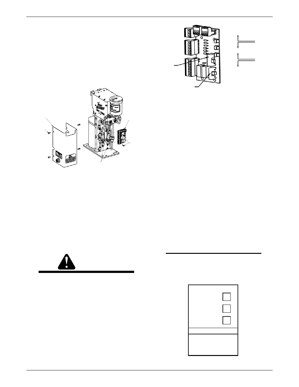
3.05 Electrical and Pneumatic Controls
Access
Ensure that the power is off and disconnected, and air
supply is off before removing logic cover.
To gain access to the circuit board and pneumatic manifold,
the logic cover must be removed. To free the logic cover
loosen four 10-24 button head screws and slide cover
away from cleaning station being careful not to disconnect
the interface connections from circuit board.
3.06 Logic Inverse
The QRC
TM
-2000 Nozzle Cleaning Station comes from the
factory set for sourcing (high) +24 V DC input or output.
Some installations may require the opposite of this or 0
V DC sinking (low) input or output.
Accessing the circuit board is necessary to switch from
sourcing to sinking input/output. On the lower right hand
corner of the circuit board are two switches that need to be
set to correspond to the input/output signal requirement
as shown.
CAUTION
do not switch circuit board sourcing and
sinking switches with power on. damage will
occur. only move switches with power off.
To operate the unit ON sinking connection, switch SW1
must be in the down position, and switch SW2 must
be in the up position. To operate the unit ON sourcing
connection, reverse the position of the switches. Refer
to diagram shown on Figure 5.
SW2
SWITCH 2 (SW2) OUTPUT
JAWS UNCLAMPED
SINKING (UP)
SOURCING (DOWN)
SOURCING (UP)
SINKING (DOWN)
SWITCH 1 (SW1) INPUT START
SIGNAL
SW1
Figure 5
3.07 LED Indicators
The LED indicators located on the side of the logic
cover, supply visual information regarding cycle status.
This information may be used for both installation and
maintenance to verify proper operation. The LED indicates
the cleaning sequence as follows:
Unclamped - On
Indicates that the clamp cylinder is fully extended, opening
the nozzle clamp block and supplying an output signal that
the reamer cycle is complete.
Reamer Ahead - Off
Indicates that the lift cylinder is fully extended putting the
reamer blade at the top of its reaming stroke and activating
the upper limit switch on the circuit board.
Reamer home - On
Indicates that the lift cylinder has fully retracted, placing
the reamer blade at the bottom of its stroke (home
position), and has activated the lower limit switch on the
circuit board.
NOTE
both the unclamped and Reamer home lights
must be on for the unit to start the cleaning
process.
CLEANING SEQUENCE
UNCLAMPED
REAMER AHEAD
REAMER HOME
CAUTION
ENSURE PROPER INTERFACE
HAS BEEN MADE OR DAMAGE
MAY OCCUR. READ TECHNICAL
GUIDE BEFORE START-UP.
Figure 6
LOGIC
COVER
NO. 10-24
X 1/2” LG.
BUTTON
HEAD
SCREW
(4 EA.)
SOLENOID
VALVE (2 EA)
CIRCUIT
BOARD
NO. 10-24
X 1/2” LG.
BUTTON
HEAD
SCREW (4
EA.)
NO.
10X1/2”
LG
THREAD
FORMING
SCREW
(2 EA)
Figure 4