Nozzle cleaning station, 09 tweco, Robotic nozzles vs. clamp block – Tweco QRC-2000 User Manual
Page 13: 10 air flow control valve, 11 nozzle and insertion parameter
nozzle cleaning station
3-11
SM-QRC-2000
inStAllAtion And opeRAtion
The other variable part in the QRC
TM
-2000 Nozzle Cleaning
Station is the clamp block set. There are five clamp blocks
available. Please refer to Tables 2 and 3.
The clamp block “B” comes assembled on all QRC
TM
-2000
Nozzle Cleaning Station. Clamp blocks A, C, D, and E are
also supplied with the unit.
Table 2: QRC
TM
-2000 Clamp Blocks List
Clamp Block O. D.
Fits Nizzels
QRC2102-A
.938” (23,8mm)
QRC2102-B
1” (25,4mm)
QRC2102-C
1.062” (27,0mm)
QRC2102-D
1.125” (28,6mm)
QRC2102-E
.875” (22,2mm)
QRC2102-F
.787” (20,0mm)
Table 3: Tweco
®
Robotic Nozzles vs. Clamp Block
Nozzle
Nozzle O.D.
Clamp Block
REL21 Series
.875” (22,2mm)
QRC-2102-E
REL24CT Series 1” (25,4mm)
QRC-2102-B
RWC24 Series
1” (25,4mm)
QRC-2102-B
RWC26 Series
1.062” (27,0mm)
QRC-2102-C
3.09 Tweco
®
Robotic Nozzles vs. Clamp Block
Program the robot to position the Mig nozzle directly above
and centered to the reamer blade above the QRC
TM
-2000.
Insert the nozzle to the required depth to allow complete
cleaning of the tip and nozzle without damaging the torch
consumable parts. (Please refer to section 3.11).
At this time the cycle start signal (pulse .5 to 1.0 seconds)
should be sent to the QRC
TM
-2000 from the robotic
controller. Then the QRC
TM
-2000 will clamp the nozzle and
perform the cleaning operation.
Once the reamer completes the cleaning cycle, the cleaning
station will send a cycle complete signal back to the robot
controller. At this time, the torch is removed from the
QRC
TM
-2000 and the work cycle continues.
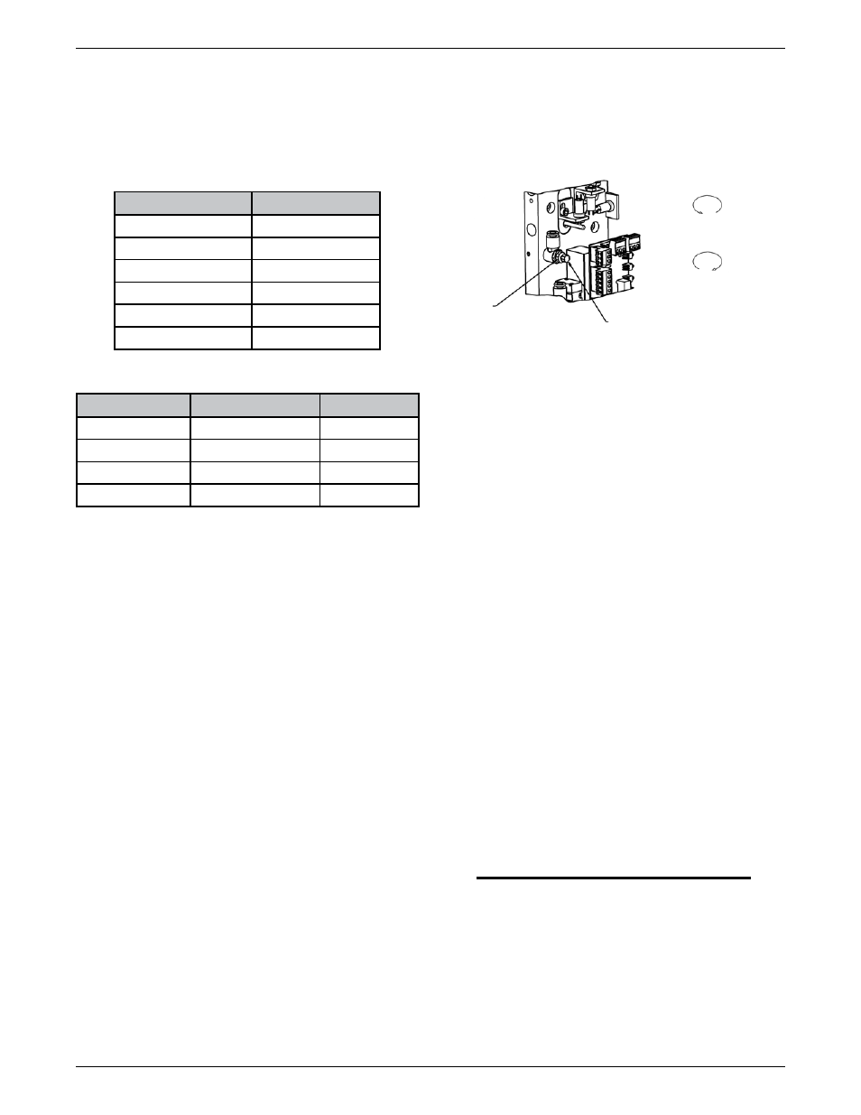
3.10 Air Flow Control Valve
The air flow control valve provides an adjustment for the
reamer blade feed rate. The amount of spatter buildup
will determine the required reamer blade feed rate. The
heavier the spatter, the slower the reamer blade feed
rate that should be used. If a smaller amount of spatter
accumulates, the feed rate can be set faster.
Adjusting the air flow control valve:
There is an air flow control valve inside the unit as
shown in Figure 8.
The feed rate may require adjusting for different
applications.
•
•
ADJUSTING
KNOB
LOCKING
NUT
INCREASE
FEED RATE
DECREASE
FEED RATE
Figure 8
3.11 Nozzle and Insertion Parameter
All QRC
TM
-2000 Nozzle Cleaning Stations come from
Tweco
®
Robotics with the QRC-100 reamer blade
(.620”/15,7mm O.D. x .422” / 10,7mm I.D.) and clamp
block “B” (QRC2102-B / 1”(25,4mm)).
Please make sure that the reamer blade and clamp block
fit the need of your application.
Setting up the Torch with Gauges
There are three sizes of gauges (1/2” (12,7mm), 5/8”
(15,9mm) and 3/4” (19,1mm)). These gauges are
available as a set under Part No. QRC
TM
-PG2.
Determine O.D. of reamer blade being used.
Slip proper gauge on O.D. of reamer blade.
Screw in tip index shaft.
Determine O.D. of contact tip being used.
Slip proper alignment sleeve on pointer.
Bring torch down to where the I.D. of contact tip
touches pointer, push alignment sleeve up and over
contact tip to gauge if torch is set at 90 degrees.
Once this is established, back the torch off from the
pointer to allow room to remove the pointer and
alignment sleeve.
Bring the torch back down to where the nozzle
touches top of the gauge.
This allows the programmer to set up for the stroke
of the reamer blade in the cleaning sequence.
NOTE
using a flush or protruded nozzle, adjust the
reamer blade stroke, leaving a gap between
the nozzle and the top of the gauge. for
flush nozzles: leave a 1/8” (3,2mm) gap.
for protruded nozzles: leave a 1/4” (6,4mm)
gap.
•
•
•
•
•
•
•
•
•
•
To increase the reamer blade feed rate, unscrew the
nut and rotate the valve knob counter-clockwise.
After the adjustment, lock the valve knob nut.
To decrease the reamer blade feed rate, unscrew the
nut and rotate the valve knob clockwise. After the
adjustment, lock the valve knob nut.
•
•