Transmig 400 i – Tweco 400i Transmig User Manual
Page 23
TRANSMIG 400 i
July 18, 2008
4-1
SECTION 4:
OPERATION
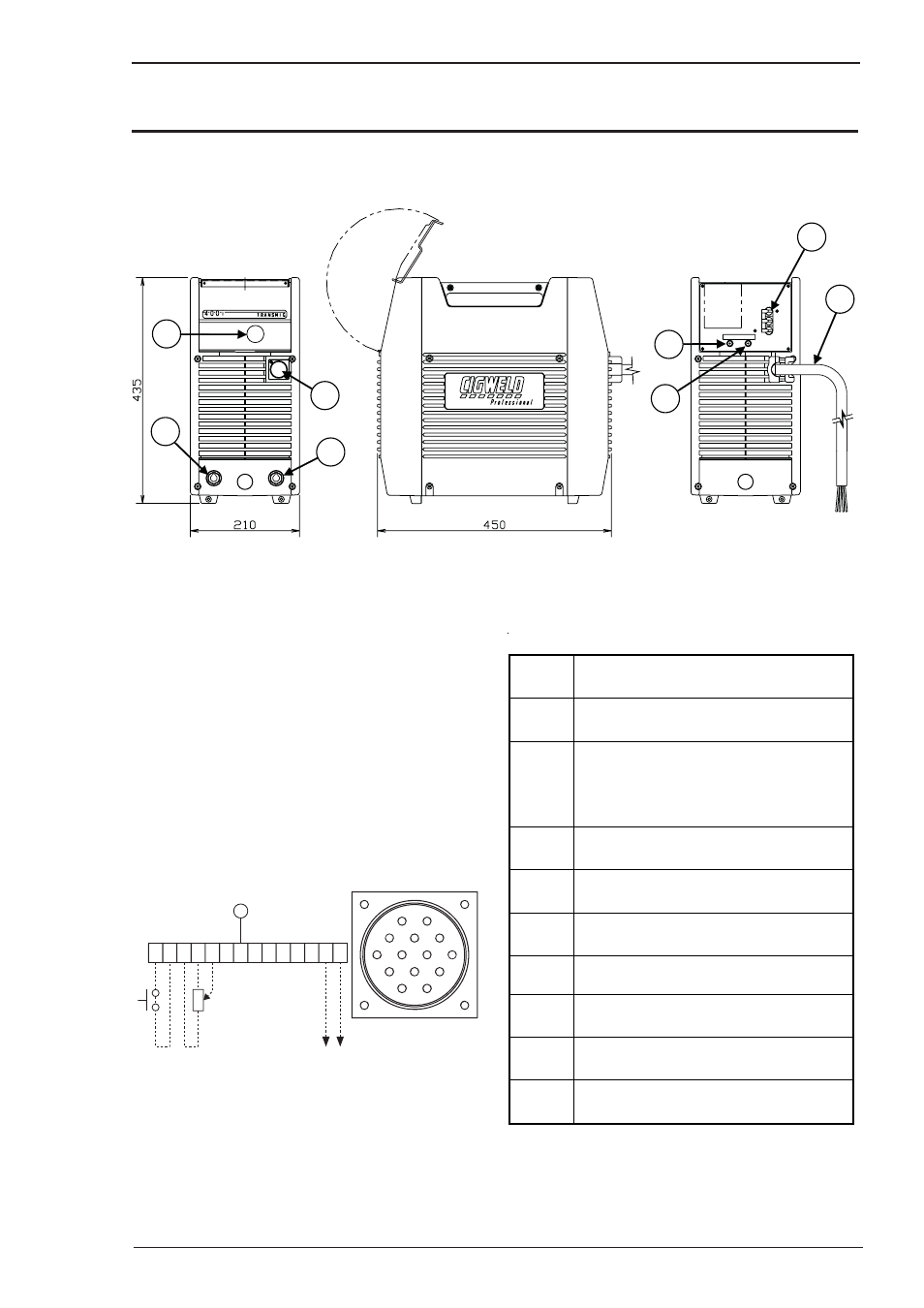
4.01 Transmig 400 i Controls
Art A-08355_AB
7
8
6
5
2
1
3
4
Figure 4-1: Transmig 400 i Power Source
1. Control Knob:
This control sets the selected weld
parameter, rotating it clockwise increases the
parameter that is indicated on the digital meter.
Pushing the knob inward displays the actual welding
voltage.
2 . Remote Control Socket:
The 14 pin Remote
Control Socket is used to connect remote current
control devices to the welding Power Source. To
make connections, align keyway, insert plug, and
r
otate threaded collar fully clockwise.
A
J
B
K
I
C L
N H
D M G
F
E
A B C
E
Front view of 14
Socket Receptacle
5k ohms
Art # A-07653_AB
D E F
H I J K L M N
G
Figure 4-2: 14-Pin Socket Receptacle
Socket
Pin
Function
A
Torch Switch Input (24V) to (connect
pins A & B to turn on welding current).
Torch Switch Input (0V) to energize
weld
B
current (connect pins A & B to turn on
welding current).
C
5k ohm (maximum) connection to 5k
ohm remote control potentiometer.
D
Zero ohm (minimum) connection to 5k
ohm remote control potentiometer.
E
Wiper arm connection to 5k ohm
r
emote control potentiometer.
G
Mains Earth.
F,H,I,J,
K,L
Not Used.
M
OK to move current detect signal for
r
obotics applications.
N
OK to move current detect signal for
r
obotics applications.
Table 4-1: Socket Pin Functions