Tweco 350 4R Wirefeeder User Manual
Page 36
5-4
Manual 0-5182
weldskill 250, 350 set up
Setup
trode wire manufacturer. (Power Source Torch Polarity Lead not required to be connected when using
wirefeeder)
B. Connect the control cable from the Wirefeeder to the control socket on the Power Source.
C. Fit the gas regulator and flowmeter to the gas cylinder then connect the gas hose from the rear of the
Wirefeeder to the Flowmeter outlet.
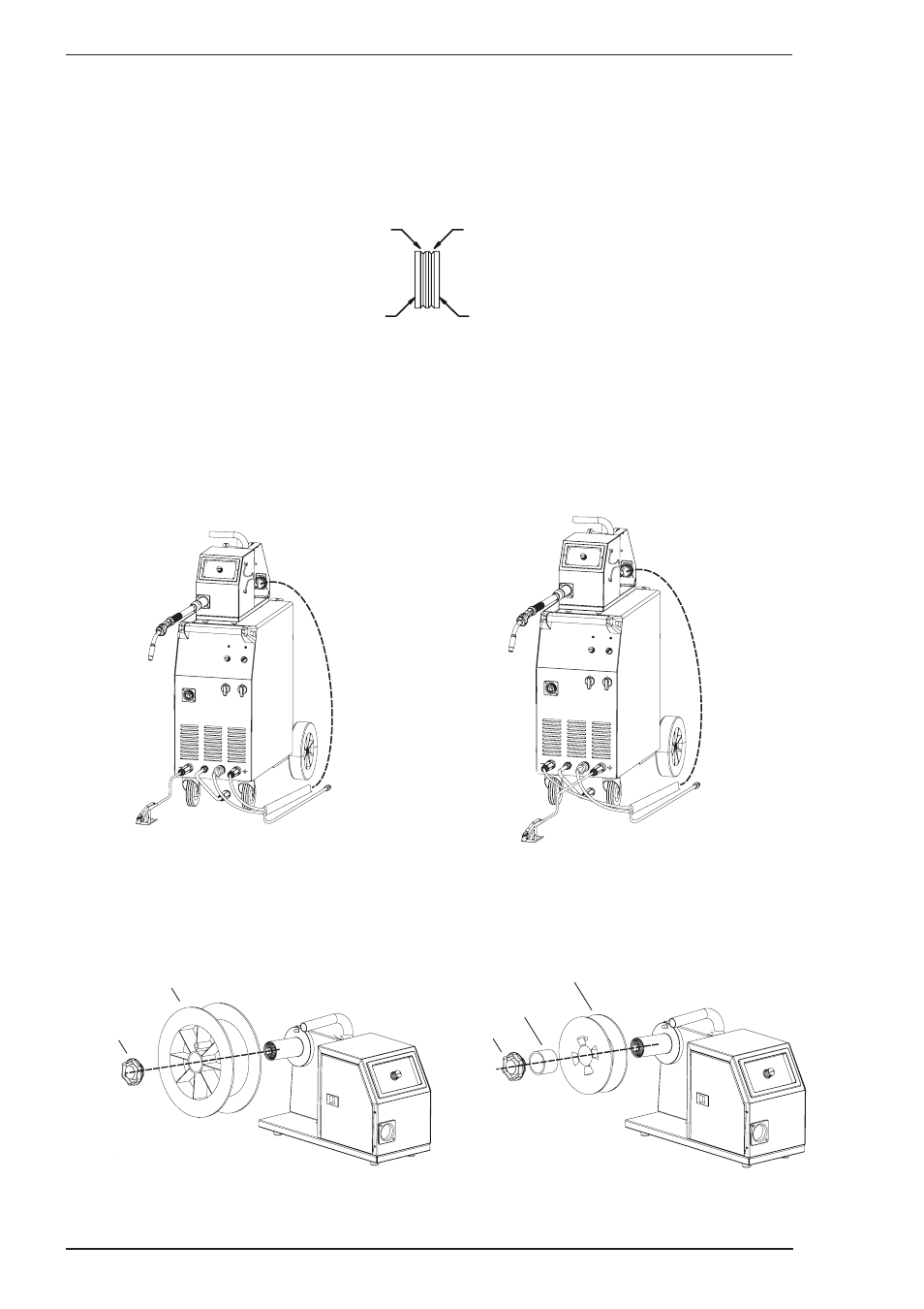
D. Dual groove feed rollers are supplied as standard. They can accommodate 0.9/1.2mm diameter hard
wires. Select the roller required with the chosen wire size marking facing outwards.
GROOVE “B”
GROOVE “A”
GROOVE “A” SIZE
GROOVE “B” SIZE
Art # A-08739
E. Fit the electrode wire spool to the wirefeeder wire reel hub. (Note that there is an adaptor supplied when
using 200mm diameter wire spools). Ensure that the drive dog-pin engages the mating hole in the wire
spool. Push the spool securing clip into place to retain the wire spool securely. The electrode wire should
feed from the bottom of the spool.
F. MIG Torch, EURO MIG Torch Connection
Fit the MIG Torch to the Wirefeeder by pushing the torch connector into the brass torch adaptor and
screwing the plastic torch nut clockwise to secure the torch to the torch adaptor. Remove the contact tip
from the torch handset.
Art # A-09924_AC
Setup for MIG (GMAW) Welding
with Gasless MIG Wire
Setup for MIG (GMAW) Welding
with Gas Shielded MIG Wire
300mm Wire spool installation
200mm Wire spool installation
TO SHIELDING GAS
REGULATOR
TO SHIELDING GAS
REGULATOR
200mm Diameter
Wire Spool
300mm Diameter
Wire Spool
Spool Hub Nut
200mm Diameter
Wire Spool Adaptor
Spool Hub Nut
Figure 5-2 WeldSkill 250 & 350 WF Setup and WF Spool Hub