Fabricator 181i – Tweco 181i Fabricator User Manual
Page 52
Fabricator 181i
INSTALLATION, OPERATION AND SETUP
3-22
Manual 0-5191
Art #
A-10362
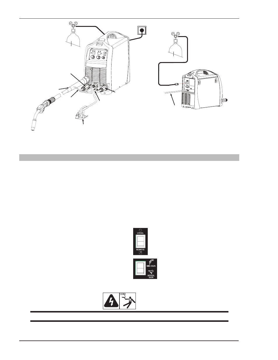
Shielding Gas Hose Fitted
with 5/8"-18 UNF
connection
Primary Cord
Work Lead
Negative Welding
Terminal (-)
Positive Welding
Terminal (+)
MIG Gun
Polarity Lead
MIG Gun
8 pin Plug
Secure the gas cylinder
in an upright position
by chaining it to a
stationary support to
prevent falling or tipping.
Figure 3-16: Setup for MIG Welding with Gas Shielded MIG Wire
3.21 Setup for MIG (FCAW) Welding with Flux Core (Gasless) Wire
A. Select MIG mode with the process selection control (refer to Section 3.10.12 for further information).
B. Connect the MIG Gun Polarity Lead to the negative welding terminal (-). If in doubt, consult the electrode
wire manufacturer. Welding current flows from the Power Source via heavy duty bayonet type terminals. It is
essential, however, that the male plug is inserted and turned securely to achieve a sound electrical connection.
C. Connect the work lead to the positive welding terminal (+). If in doubt, consult the electrode wire manufacturer.
Welding current flows from the Power Source via heavy duty bayonet type terminals. It is essential, however,
that the male plug is inserted and turned securely to achieve a sound electrical connection.
D. Refer to the Weld Guide located on the inside of the wirefeed compartment door for further information.
E. Switch the LOCAL/REMOTE switch inside the
wire feed compartment to LOCAL to use the
Power Sources Wirespeed and Voltage controls.
F. Switch the MIG GUN/SPOOL GUN switch inside
the wire feed compartment to MIG GUN.
WARNING
Before connecting the work clamp to the work make sure the Electricity Supply is switched OFF.