Fabricator 181i, 05 electromagnetic compatibility – Tweco 181i Fabricator User Manual
Page 33
Fabricator 181i
Manual 0-51
91
3-3
INSTALLATION, OPERATION AND SETUP
Input Power
Each unit incorporates an INRUSH circuit. When the MAIN CIRCUIT SWITCH is turned ON, the inrush circuit
provides pre-charging for the input capacitors. A relay in the Power Control Assembly (PCA) will turn ON after the
input capacitors have charged to operating voltage (after approximately 5 seconds)
NOTE
Damage to the PCA could occur if 265V AC or higher is applied to the Primary Power Cord.
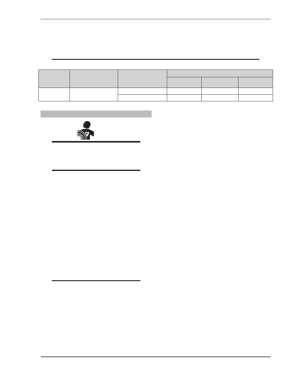
Model
Primary Supply
Cord Size
(Factory Fitted)
Minimum Primary
Current Circuit Size
(Vin/Amps)
Current & Duty Cycle
MIG (GMAW/
FCAW)
STICK (SMAW)
LIFT TIG
(GTAW)
Fabricator
181i
12 AWG (3.3mm²)
208-230V/40A
180A @ 20%
175A @ 20%
208-230V/25A
175A @ 25%
Table 3-2: Primary Circuit Sizes to Achieve Maximum Current
3.05 Electromagnetic Compatibility
WARNING
Extra precautions for Electromagnetic
Compatibility may be required when this
Welding Power Source is used in a domestic
situation.
A. Installation and Use - Users Responsibility
The user is responsible for installing and using the
welding equipment according to the manufacturer’s
instructions. If electromagnetic disturbances are
detected then it shall be the responsibility of the user
of the welding equipment to resolve the situation
with the technical assistance of the manufacturer.
In some cases this remedial action may be as
simple as earthing the welding circuit, see NOTE
below. In other cases it could involve constructing
an electromagnetic screen enclosing the Welding
Power Source and the work, complete with
associated input filters. In all cases, electromagnetic
disturbances shall be reduced to the point where
they are no longer troublesome.
NOTE
The welding circuit may or may not be
earthed for safety reasons. Changing the
earthing arrangements should only be
authorized by a person who is competent to
assess whether the changes will increase the
risk of injury, e.g. by allowing parallel welding
current return paths which may damage the
earth circuits of other equipment. Further
guidance is given in EN 60974-13 Arc
Welding Equipment - Installation and use
(under preparation).
B. Assessment of Area
Before installing welding equipment, the user shall
make an assessment of potential electromagnetic
problems in the surrounding area. The following
shall be taken into account
1. Other supply cables, control cables, signaling
and telephone cables; above, below and adjacent
to the welding equipment.
2. Radio and television transmitters and receivers.
3. Computer and other control equipment.
4. Safety critical equipment, e.g. guarding of
industrial equipment.
5. The health of people around, e.g. the use of
pacemakers and hearing aids.
6. Equipment used for calibration and
measurement.
7. The time of day that welding or other activities
are to be carried out.
8. The immunity of other equipment in the
environment: the user shall ensure that other
equipment being used in the environment
is compatible: this may require additional
protection measures.
The size of the surrounding area to be considered
will depend on the structure of the building and other
activities that are taking place. The surrounding area
may extend beyond the boundaries of the premises.