Ultra-cut 100 xt, 20 connecting torch – Tweco 100 XT Ultra-Cut Plasma Cutting System User Manual
Page 56
ULTRA-CUT 100 XT
3�34
INSTALLATION
Manual 0-5272
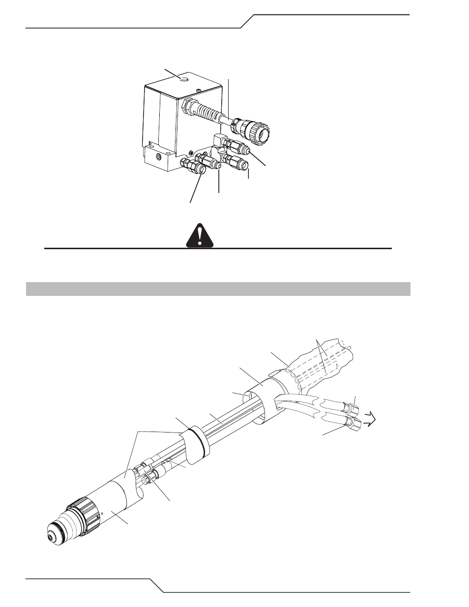
3. Connect the gas supply lines and the control cable connector from the Gas Control Module to the Valve Kit as
shown. Hold the check valves stationary while attaching the gas lines.
Control Cable
Plasma Gas Inlet
Shield Gas Inlet
Preflow Gas Inlet
WMS™ Inlet
Art # A-07646
Exhaust Muffler
CAUTION
Hold all fittings stationary while attaching hoses or leaks can be created. Side pressure can break the check valves
or weaken their connection to the torch valve assembly. All fittings must be checked for leaks after assembly.
3.20 Connecting Torch
Connect the Torch as follows:
Art # A-09198
Pilot Lead Connector
Torch Head Assembly
Mounting Tube
O-Ring
Torch Leads End Cap
Plasma Gas
(Left Hand Thread)
Shield Gas
(Right Hand Thread)
Coolant Supply
&
Power Lead (-)
Pilot Lead
Coolant Supply,
Coolant Return,
and Pilot Leads
Leads Cover
Groove for O-Ring
To Torch Valve
1. Lay out the torch leads on a clean, dry working surface.
2. Hold the Torch Leads End Cap stationary. Pull approximately 18” (0.5 m) of leads through the End Cap.