04 troubleshooting specific problems – Tweco SC10 User Manual
Page 34
CUSTOMER/OPERATOR SERVICE
5-4
Manual 0-2479
MODE
LIFTER SPEED
UP
DOWN
J3-8
J3-12
J3-17
J3-14
J3-13
A-01076
The measurement should be less than 200 to 300 ohms
when the switch is pushed.
If the measurement is not correct the switch is faulty;
replace front panel assembly.
If the measurement is correct then the Standoff Con-
trol PC Board is faulty; replace the complete Stand-
off Control Assembly.
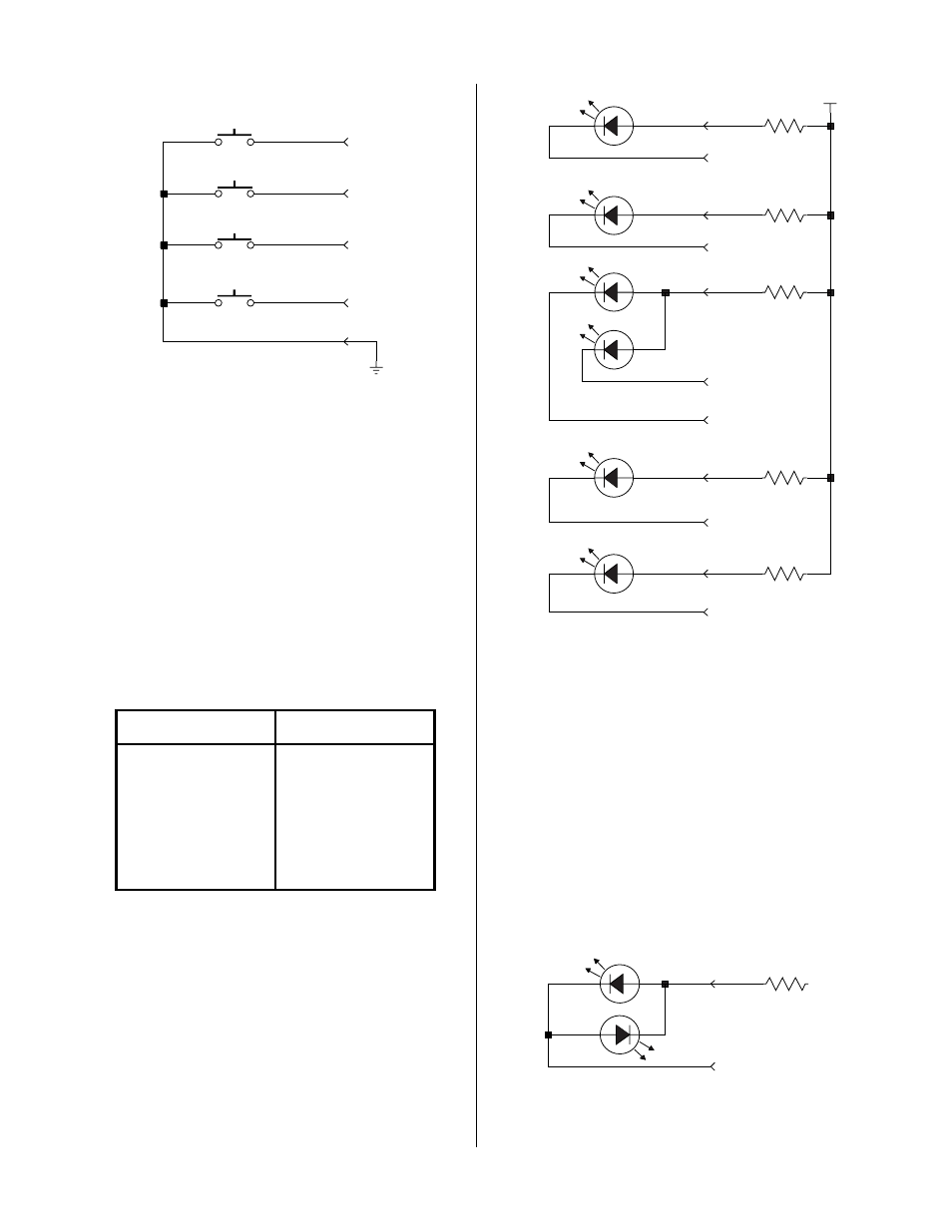
C. Front Panel Indicator Tests
For all indicators, except TORCH UP and TORCH
DOWN, measure the dc voltage from PC Board com-
mon (TP1) to the J3 pin for the indicator cathode per
the following:
I n d ica t o r
C a t h o d e P in #
P L A S M A O N
J 3 -3
F I N D H T
J 3 -6
A U T O H T
J 3 -7
H I
J 3 -9
L O W
J 3 -1 1
AUTO HT
FIND HT
HI
LOW
PLASMA ON
THC ACTIVE
+V1
J3-4
J3-7
J3-5
J3-6
J3-10
J3-11
J3-9
J3-2
J3-3
J3-18
J3-19
A-01077
If the voltage is near 15 vdc momentarily jumper the
cathode to TP1. If the indicator does not come ON
momentarily the indicator is faulty. Replace the front
panel assembly.
If the indicator comes ON the Standoff Control PC
Board is faulty, assuming the system is working nor-
mally.
For the UP and DOWN indicators, if the motor moves
up and down manually and if one indicator works
normally but not the other, it is faulty and front panel
assembly should be replaced. If neither works mea-
sure from TP1 to J3-15 while moving the motor up
and down. If the voltage is zero the Standoff Control
SC10 PC Board is faulty. If it is higher, can be as high
as +/-20v, the front panel assembly is faulty.
A-01078
UP
DOWN
J3-15
J3-15