09 internal selections, 10 external cable connections – Tweco SC10 User Manual
Page 24
INSTALLATION PROCEDURES
3-8
Manual 0-2479
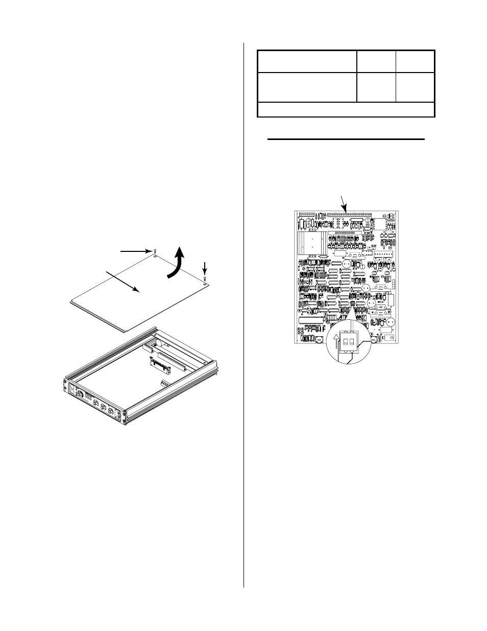
3.09 Internal Selections
A. Switch (SW1) Selection
The Standoff Control Assembly has one internal switch
(SW1) that is used for some plasma cutting systems with-
out an arc transfer or motion signal. Turning ON SW1-1
and SW1-2 will generate the signal as soon as the pilot
arc voltage drops from open circuit to under 195v. This
occurs as soon as pilot is initiated so the PIERCE DELAY
should be used to delay the motion signal. This will al-
low time for arc transfer and piercing. Switch SW1 is not
needed for the TD-750 System and both positions should
be in the OFF position.
To check or change the switch selection use the following
procedure:
1. Remove the two cover mounting screws on the top of
the Standoff Accessory.
PLASM
A O
N
ARC VOLTS
RE
MO
TE
ST
AN
DO
FF
CO
NT
RO
L
T.H.C. A
CTIVE
PIER
CE
HT (i
nche
s)
0.1
0.3
0.4
0.5
0.2
END
OF C
UT
RET
RAC
T (%
)
0
25
75
100
UP
DN
TOR
CH
TORCH
MO
DE
MODE
LIFT
ER
LIFTER
SPE
ED
SPEED
PIE
RCE
DEL
AY (s
ec)
0.5
1
2
3
0.75
0.25
0.1
AU
TO
HT
FIN
D
HT
HI
LO
A-00689
Screw
Screw
Cover
Figure 3-15 Cover Removal
2. Remove the enclosure cover by lifting straight up at
the rear of the cover and pulling it towards the rear of
the unit. The front edge of the cover fits under a lip
on the front panel assembly.
3. Identify internal switch SW1 and confirm that the
switch is set for the desired system as follows:
Syst e m
SW 1 -1
SW 1 -2
O t h e r Syst e m s
O N
O N
T D -7 5 0 Syste m s
O F F *
O F F *
* = F a ct o ry Se tt in g
NOTE
Refer to Section 4.04-E for operation when start-
ing the the cutting operation off the plate (work-
piece).
Standoff Control
PC Board Assembly
A-00861
SW1
Type System
Selection
2
1
ON
Figure 3-16 Switch SW1 Location
B. J11 Isolated CNC Interface
For the TD-750 System the CNC interface is through the
Remote Control. Do not use J11 on the Standoff Control.
For other systems an isolated START, standoff inhibit
(CSD) and motion (OK-To-Move) selectable for contact
closure or 24 VAC is available at J11.
3.10 External Cable Connections
The Standoff Control has only one output connector on
the rear panel. The Lifter Motor Control Cable is con-
nected to this output. The other end of the cable is con-
nected to the lifter motor equipment.
Signals include drive (up to +/-20 vdc), tach (0 to +/- 15
vdc) and normally closed (NC) TORCH ON WORK
switch.